
Tensioning mechanism and rotary cultivator

A technology of tensioning mechanism and rotary cultivator, which is applied in the direction of agricultural machinery and implements, tillage implements, etc., to achieve the effect of convenient operation, not easy to loosen, and strong practicability

Pending Publication Date: 2018-01-26
HUNAN LONGZHOU FARM EQUIP HLDG CO LTD
View PDF15 Cites 1 Cited by
  • Summary
  • Abstract
  • Description
  • Claims
  • Application Information

AI Technical Summary

Problems solved by technology

[0006] In view of this, in order to engage and separate the power of the second transmission mechanism, make the operation convenient and labor-saving, and solve the problems of remote operation, etc., the present invention proposes a tensioning mechanism, including a bracket, an operating rod, a pull rod, a swing arm, a first rotating arm, the second pivoting arm, the bracket is fixed on the chassis, the two ends of the swinging arm are respectively connected with the second tensioning wheel and the chassis, the first pivoting arm and the second pivoting arm are connected by a rotating shaft, the first pivoting arm is connected with the operating rod Connection, the two ends of the pull rod are respectively connected with the second swing arm and the swing arm; the operating lever drives the second swing arm to rotate through the first swing arm, and the second swing arm drives the second tension wheel to swing up and down through the pull rod and swing arm

Method used


Image

  • Tensioning mechanism and rotary cultivator
  • Tensioning mechanism and rotary cultivator
  • Tensioning mechanism and rotary cultivator

Examples


Embodiment Construction

[0041] It should be noted that, in the case of no conflict, the embodiments of the present invention and the features in the embodiments can be combined with each other. The present invention will be described in detail below with reference to the accompanying drawings and examples.

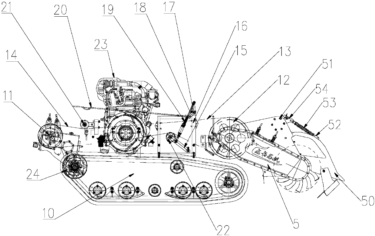
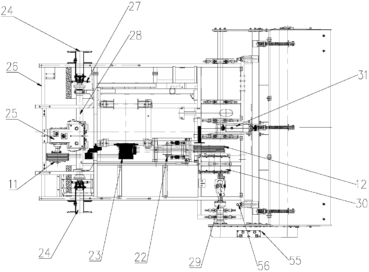
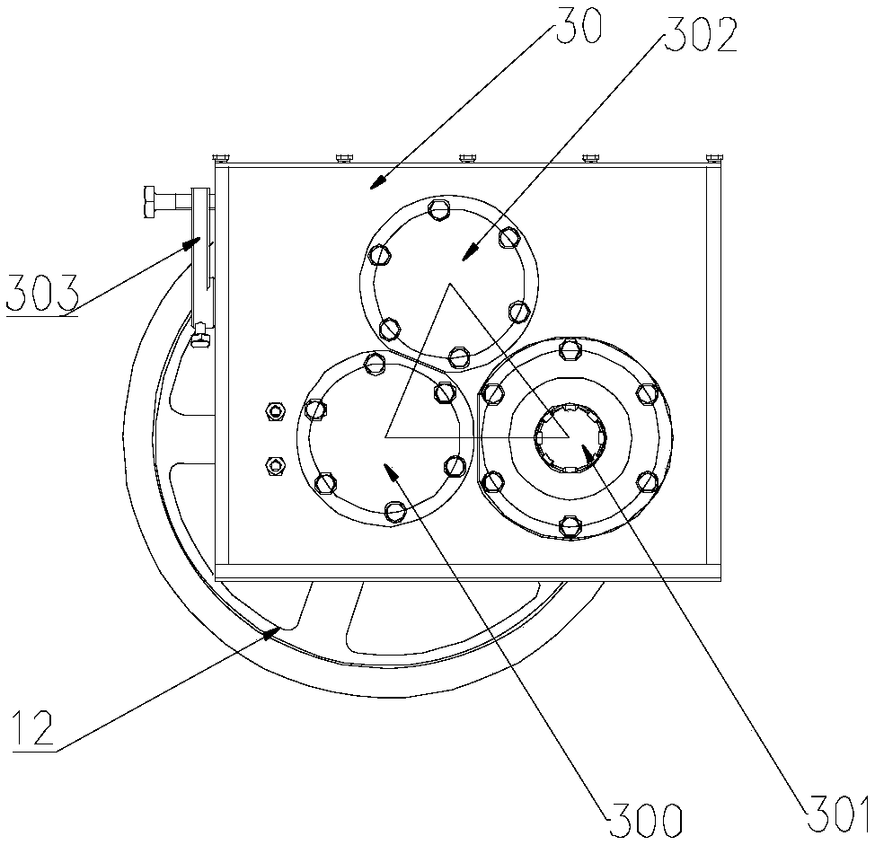
[0042] like Figure 1 to Figure 13 As shown, the present invention preferably has a combination structure for fastening and anti-loosening of driving wheels and a rotary tiller. The hinge mentioned in the present invention refers to the connection structures that can rotate with each other.

[0043] like figure 1 Shown, a kind of rotary tiller comprises a rotary tiller chassis and a rotary tiller 5, the rotary tiller 5 is installed at the rear of the rotary tiller chassis, and a counterweight (not shown in the figure) is installed at the front of the rotary tiller chassis out). The counterweight can balance the front, back, left and right sides of the rotary tiller to ensure the smooth operat...


PUM


Abstract

The invention discloses a tensioning mechanism and a rotary cultivator. The tensioning mechanism comprises a support, an operation rod, a pull rod, a swing arm, a first rotation arm and a second rotation arm, the support is fixed to a bottom rack, and two ends of the swing arm are connected with a second tensioning wheel and the bottom rack respectively; the first rotation arm is connected with the second rotation arm through a rotation shaft, the first rotation arm is connected with the operation rod, and two ends of the pull rod are connected with the second rotation arm and the swing arm respectively; the operation rod drives the second rotation arm to rotate through the first rotation arm, and the second rotation arm drives the second tensioning wheel to up and down swing through the pull rod and the swing arm. The tensioning mechanism is ingenious in structure and convenient to operate, saves labor, and generates little vibration. In the process of power separation and joining between an engine and a second transmission mechanism, the tensioning mechanism is stable and reliable.

Description

technical field [0001] The invention relates to the field of agricultural machinery, in particular to a tensioning mechanism and a rotary tiller. Background technique [0002] Rotary tiller is a kind of soil tillage machine driven by power. It has strong ability to cut soil and crush soil. It can achieve the effect of plowing and raking several times in one operation. With the continuous improvement of the level of agricultural science and technology, it has become a common method to complete the rotary tillage of farmland soil by rotary tiller. As we all know, the operating principle of the rotary tiller is to use the rotary tiller shaft to loosen and mash the mud (or clods) to achieve the purpose of tillage. The rotation direction of the existing rotary tiller shaft is a single rotary motion, which cannot be realized in positive and negative directions. to rotate. Also can only realize the one-way chain tensioning in the transmission box that drives rotary tiller shaft t...

Claims


Application Information

Patent Timeline
Patent Type & Authority Applications(China)
IPC IPC(8): A01B33/02A01B33/08
Inventor 覃新平龙学平张明辉
Owner HUNAN LONGZHOU FARM EQUIP HLDG CO LTD
Learn More