

Method and device for controlling idling speed of engine
A technology of engine idle speed and idle speed, applied in engine control, machine/engine, electrical control, etc., to solve problems such as vehicle battery power loss, inability to start, engine idle jitter or flameout, etc.
- Summary
- Abstract
- Description
- Claims
- Application Information
AI Technical Summary
Problems solved by technology
Method used
Image

Examples
no. 1 example
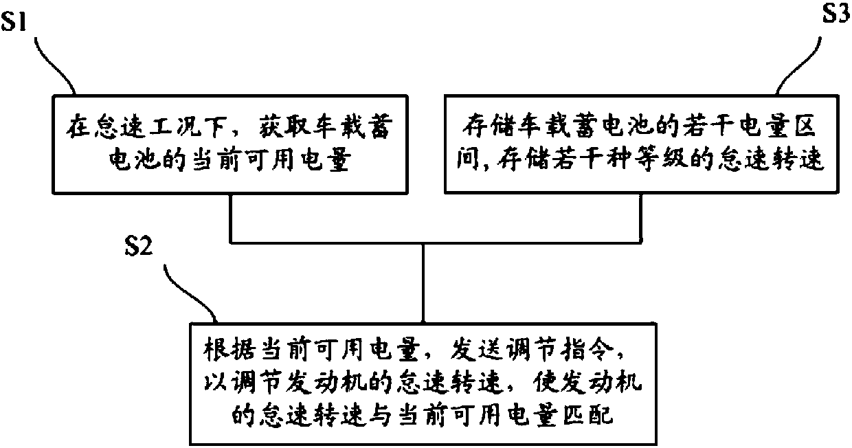
[0056] An embodiment of the present invention provides a method for controlling the idle speed of the engine, such as figure 1 shown, including the following steps:
[0057] S1: Obtain the current available power of the on-board battery under idling conditions;
[0058] S2: According to the current available power, send an adjustment command to adjust the idle speed of the engine so that the idle speed of the engine matches the current available power;
[0059] Wherein, the idle speed is inversely correlated with the current available power.
[0060] Due to the transmission connection between the generator and the vehicle engine, the two have a certain speed ratio, and the vehicle-mounted alternator is an approximate constant voltage source, and the excitation current is generally controlled by a regulator to stabilize the output voltage at a certain value. The greater the vehicle load, the greater the output current required by the generator, but the maximum output current ...
no. 2 example
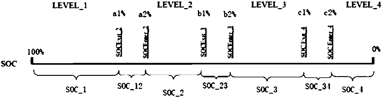
[0088] The difference between this embodiment and the first embodiment is that the intervals between the several power intervals are discontinuous, and there is an interval between two adjacent electric intervals, and this interval is defined as a transition interval.
[0089] Such as image 3, choose 100%, a1%, a2%, b1%, b2%, c1%, c2%, 0% as the critical point of each power range, where 100%>a1%>a2%>b1%>b2%>c1 %>c2%>0%. The range of power between 100% and a1% is the first power range SOC_1, the range of power between a2% and b1% is the second power range SOC_2, and the range of power between b2% and c1% is the third power interval SOC_2, and the interval of the electric power range between c2%-0% is the fourth electric power interval SOC_4.
[0090] The interval between a1% and a2% is the first transition interval SOC_12, the interval between b1% and b2% is the second transition interval SOC_23, and the interval between c1% and c2% is the third transition interval SOC_34. ...
no. 3 example
[0129] The difference between this embodiment and the second embodiment is that the method of "determining the target level" in step S22 is different.
[0130] In this embodiment, the current available power p is first compared with the power range corresponding to the idle speed one level lower, and if the result is no, then the current available power p is compared with the power range corresponding to the idle speed one level higher. Compare and finally get the target grade.
[0131] Specifically, combined with Figure 6 , the steps of step S22 "determining the target level" include:
[0132] S221: Obtain the current idle speed;
[0133] S222: Determine the current level corresponding to the current idle speed;
[0134] S223: Determine the power range corresponding to the idle speed one level higher than the current level; determine the power range corresponding to the idle speed one level lower than the current level;
[0135] S224: Judging whether the current availabl...
PUM
 Abstract
Description
Claims
Application Information