Engine exhaust brake control device and method and engineering vehicle

An exhaust braking and control device technology, applied in engine control, machine/engine, mechanical equipment, etc., to improve braking effect and prevent flameout

Inactive Publication Date: 2013-01-23
SANY AUTOMOBILE MFG CO LTD
View PDF5 Cites 16 Cited by
  • Summary
  • Abstract
  • Description
  • Claims
  • Application Information

AI Technical Summary

Problems solved by technology

[0005] In view of this, the present invention proposes an engine exhaust brake control device and method and an engineering vehicle to solve the problem that

Method used


Image

  • Engine exhaust brake control device and method and engineering vehicle

Examples


Embodiment Construction

[0022] It should be noted that, in the case of no conflict, the embodiments of the present invention and the features in the embodiments can be combined with each other. The present invention will be described in detail below with reference to the accompanying drawings and examples.

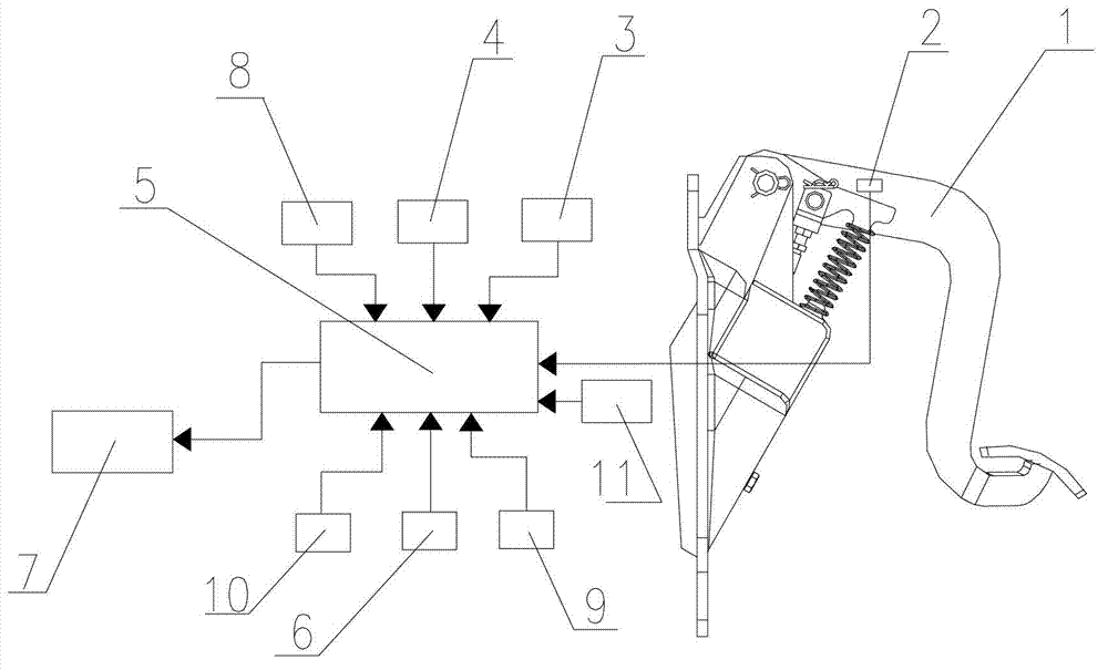
[0023] Such as figure 1 Said engine exhaust brake control device includes: controller 5, exhaust brake solenoid valve 7, clutch sensor 9, transmission neutral sensor 10, slope sensor 4, vehicle speed sensor 8, accelerator pedal sensor 11, brake pedal Sensor 2, engine speed sensor 3, engine exhaust brake cut-off switch 6. Controller 5 is controlled by acquiring clutch sensor 9, transmission neutral sensor 10, slope sensor 4, vehicle speed sensor 8, accelerator pedal sensor 11, brake pedal sensor 2, engine speed sensor 3, and engine exhaust brake cut-off switch 6 signals. The exhaust brake solenoid valve 7 is turned on and off, thereby turning on and off the engine exhaust brake. Engine exhaust ...


PUM


Abstract

The invention discloses an engine exhaust brake control method. According to the engine exhaust brake control method, a first control mode is involved; when a vehicle runs on a downhill, a gradient sensor acquires a vehicle downhill running signal and sends the signal to a controller; when the time of the vehicle downhill running signal is greater than or equal to preset time of the controller, and when a clutch of the vehicle is switched off, and a speed changer is at a driving gear position, the controller switches on an exhaust brake electromagnetic valve, and the vehicle executes engine exhaust brake; and when the gradient sensor does not output the vehicle downhill running signal, the controller switches off the exhaust brake electromagnetic valve. Whether the downhill is long can be judged according to the time duration of the downhill running signal acquired by the gradient sensor, and a function of automatically switching on engine exhaust brake can be realized.

Description

technical field [0001] The invention relates to the field of vehicle braking, in particular to an engine exhaust braking control device and method and an engineering vehicle. Background technique [0002] At present, the vehicle braking methods mainly include: disc brakes, drum brakes, eddy current brakes, and engine exhaust brakes. Disc brakes, drum brakes and eddy current brakes all brake the driving system of the vehicle, which are traditionally called service brakes. The engine exhaust brake does not directly brake the driving system of the vehicle, but uses the method of closing the engine exhaust passage, so that the engine piston is subjected to the back pressure of the gas during the exhaust stroke, preventing the engine from running and causing braking. function, so as to achieve the purpose of controlling the speed of the vehicle. Traditionally also known as engine exhaust braking. [0003] The engine exhaust brake device consists of an exhaust brake solenoid va...

Claims


Application Information

Patent Timeline
IPC IPC(8): F02D9/06F02D13/04
Inventor 张克军吴萍郑立波
Owner SANY AUTOMOBILE MFG CO LTD
Why Eureka
Try Eureka