Electronic speed control system for farm machines

Inactive Publication Date: 2005-08-11
BLUE LEAF I P
View PDF2 Cites 16 Cited by
  • Summary
  • Abstract
  • Description
  • Claims
  • Application Information

AI Technical Summary

Benefits of technology

[0006] The particular system of powering and steering self propelled farm machines by hydraulic motors at the wheels provides an opportunity for much improved vehicle speed control. The preferred embodiment of the invention uses a microprocessor to evaluate all the conditions to which the machine is sub

Problems solved by technology

Such machines are not powered by direct mechanical linkages from the engine to the drive wheels, and are not steered by changing the angle of the vertical planes of the wheels.
However, farm machines are subjected to rapidly occurring and widely varying

Method used


Image

  • Electronic speed control system for farm machines
  • Electronic speed control system for farm machines
  • Electronic speed control system for farm machines

Examples


Embodiment Construction

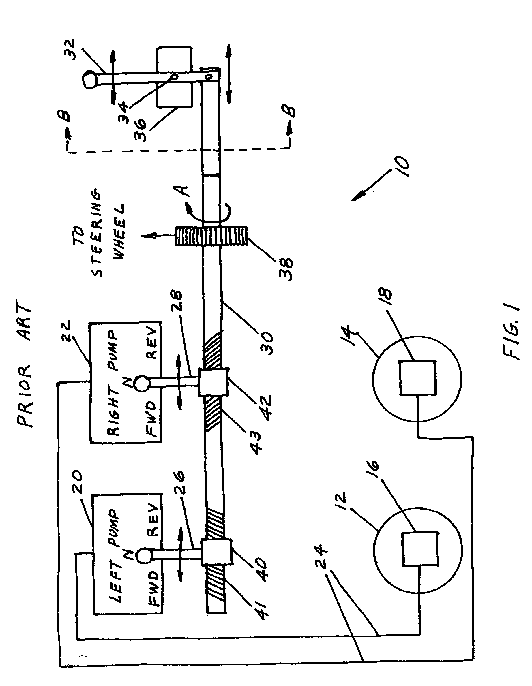
[0017]FIG. 1 is a simplified block diagram of the manual steering and speed control apparatus 10 of a typical self propelled farm machine. Motive power is delivered to left wheel 12 and right wheel 14 by hydraulic motors 16 and 18, respectively. Hydraulic motors 16 and 18 are themselves powered from left hydraulic pump 20 and right hydraulic pump 22, which are mechanically powered from the machine's engine (not shown) by conventional mechanical linkages (not shown).

[0018] Left pump 20 and right pump 22 supply hydraulic fluid under pressure to wheel motors 16 and 18 through hydraulic lines 24. Each of pumps 20 and 22 has the capability of rotating its associated wheel motor so that the powered wheel will go forward or in reverse, and if the pump is in its neutral setting, to not power the wheel at all. The three settings of pumps 20 and 22 are indicted in FIG. 1 as “FWD”, “REV”, and “N”. Moreover, pumps 20 and 22 are not simple on and off devices, but their fluid outputs vary with t...


PUM


Abstract

The apparatus is an electronic speed control for farm machines. A microprocessor is fed data on the tractor engine speed, the tractor ground speed, and the manual speed lever setting, and electronically matches the desired ground speed to the engine speed to prevent stalling the engine. Ground speed is controlled by using the microprocessor to electrically vary a control valve that replaces the usual mechanical linkage between the speed control lever and the hydraulic pumps driving the hydraulic wheel motors.

Description

BACKGROUND OF THE INVENTION [0001] This invention deals generally with farm machinery and more specifically with an electronic speed control for self propelled farm machines. [0002] It is quite interesting that large self propelled farm machines are not all powered or steered in the same manner as the road vehicles with which we are familiar. Such machines are not powered by direct mechanical linkages from the engine to the drive wheels, and are not steered by changing the angle of the vertical planes of the wheels. The wheels of many such self propelled farm machines, including large farm tractors, are coupled to their engines by hydraulic systems. The engine directly drives hydraulic pumps, and those pumps are connected by hoses to hydraulic motors that are located at and turn the wheels. Wheel speed is then controlled by changing the quantity of hydraulic fluid that the pump delivers to the wheel motor. Furthermore, to reverse the motion of the hydraulic motor and thus reverse th...

Claims


Application Information

Patent Timeline
IPC IPC(8): A01B67/00B60K31/08B60T8/32B60W10/10F16H61/28
CPCA01B67/00F16H61/2807B60W10/103B60K31/08
Inventor BERGER, JOHN G.PETERS, JEREMY DANIELCLEVENGER, JAMES T. JR.EHRHART, PHILIP J.STROSSER, RICHARD P.FOSTER, CHRISTOPHER A.
Owner BLUE LEAF I P
Why Eureka
Try Eureka