
Linear transmission part

A technology of linear transmission and components, which is applied in transmission devices, belts/chains/gears, mechanical equipment, etc., can solve the problems of increasing the difficulty of installing spare parts, poor structural rationality, limited selection of spare parts, etc., and achieve less material consumption , The overall structure is compact and the section space utilization rate is high

Pending Publication Date: 2018-01-26
GUANGDONG LYRIC ROBOT INTELLIGENT AUTOMATION CO LTD
View PDF6 Cites 0 Cited by
  • Summary
  • Abstract
  • Description
  • Claims
  • Application Information

AI Technical Summary

Problems solved by technology

[0002] Most of the existing linear transmission components are assembled by simple superimposition of components, and the rationality of the structural position is poor. The function of the section is not maximized, and the space of the section is not fully utilized. The selection of spare parts is limited, which is not conducive to the stable use and further promotion of transmission components

Method used


Image

  • Linear transmission part

Examples


Embodiment 1

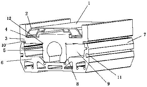
[0018] This embodiment provides a linear transmission component, including a base, a sliding table and a cover plate, and the sliding table is installed between the base and the cover plate. The cover plate is composed of a top plate 1 and a raised structure 2 arranged on both sides of the top plate 1; the slide table is a positive T-shaped structure, and a avoidance hole 12 is provided at the connection position between the horizontal part 3 and the vertical part 5 of the slide table, and the hole avoidance The setting of 12 facilitates the installation of parts and reduces the difficulty of installation. The upper surface of the horizontal part 3 of the slide table is provided with a first groove 4 that matches the raised structure 2, and the height of the first side of the first groove 4 close to the center of the horizontal part 3 is smaller than that of the first groove 4 away from the horizontal part. 3, the height of the second side away from the center of the transvers...

Embodiment 2

[0020] This embodiment is similar to Embodiment 1, and further, the lower surface of the transverse part 3 of the slide table is provided with a third groove 10 at a position corresponding to the top of the side wall 7, and the third groove 10 matches the top of the side wall 7 , the arrangement of the third groove 10 further improves the stability of the connection between the slide table and the base.

[0021] In addition, there is also a second protrusion inside the raised structure 2 on the cover plate, the second raised structure is connected to the raised structure 2, the size of the second raised structure is smaller than the size of the raised structure 2, and the raised structure 2 and the inside of the second protruding structure adopt a hollow design, which reduces the weight of the cover to a certain extent, saves materials and ensures its mechanical strength.

Embodiment 3

[0023] This embodiment is similar to Embodiment 1 or 2. Further, the cavity structure provided inside the support base 6 specifically includes a rectangular cavity structure, two triangular cavity structures and two trapezoidal cavity structures, and the rectangular cavity structure Located directly below the vertical part 5, the triangular cavity structure and the trapezoidal cavity structure are symmetrically distributed on both sides of the rectangular cavity structure, and the triangular cavity structure is located between the rectangular cavity structure and the trapezoidal cavity structure, and the trapezoidal cavity structure Mounting holes are provided around the structure. The supporting bottom plate 6 contains a plurality of cavity structures equipped with mounting holes, so that the base provides convenient space for the installation of components while ensuring the connection strength.


PUM


Abstract

The invention relates to a linear transmission part. The linear transmission part comprises a pedestal, a slide table and a cover plate, wherein the slide table is mounted between the pedestal and thecover plate; the cover plate consists of a top plate and convex structures at the two sides of the top plate; the slide table is of a regular T-shaped structure; first grooves matched with the convexstructures are formed in the upper surface of the transverse part of the slide table; a through hole for mounting a lead screw is arranged in the vertical part of the slide table; the pedestal is ofa U-shaped structure, and comprises a supporting base and side walls connected with the two sides of the supporting base; a second groove matched with the lower surface of the vertical part is formedin the inner surface of the supporting base; sum of the depth of the second groove and the height of the side walls is matched with the height of the vertical part; and guide rail placing cavities arearranged at the two sides of the vertical part through the slide table and the pedestal. The linear transmission part disclosed by the invention consists of the pedestal, the slide table and the cover plate, the through hole for mounting the lead screw is formed in the vertical part by the assembled transmission part, and the guide rail placing cavities are formed at the two sides of the verticalpart, so that the integral structure is relatively compact, material consumption is less, and a section space utilization rate is high.

Description

technical field [0001] The invention relates to a transmission component, in particular to a linear transmission component with reasonable structure and sufficient cross-sectional space utilization. Background technique [0002] Most of the existing linear transmission parts are assembled by simple superimposition of parts, the rationality of the structural position is poor, the function of the section is not maximized, and the space of the section is not fully utilized. The selection of spare parts is limited, which is not conducive to the stable use and further promotion of transmission components. Contents of the invention [0003] In order to solve the above technical problems, the present invention provides a linear transmission component with reasonable structure and sufficient cross-sectional space utilization. [0004] A linear transmission component, comprising a base, a slide table and a cover plate, the slide table is installed between the base and the cover pl...

Claims


Application Information

Patent Timeline
Patent Type & Authority Applications(China)
IPC IPC(8): F16H25/24
Inventor 周俊雄周俊杰邓慧怡黄辉林捷李湧鑫林峰
Owner GUANGDONG LYRIC ROBOT INTELLIGENT AUTOMATION CO LTD
Learn More