
Laser type vehicle detecting method and device thereof

A vehicle detection and laser technology, applied in the field of intelligent transportation, can solve the problems of complex application environment, increase the cost of purchasing equipment, increase the cost of maintenance and purchasing equipment, etc., and achieve the effect of reducing costs and improving service life.

Inactive Publication Date: 2018-01-26
WUHAN WANJI INFORMATION TECH
View PDF8 Cites 0 Cited by
  • Summary
  • Abstract
  • Description
  • Claims
  • Application Information

AI Technical Summary

Problems solved by technology

The scanning laser ranging sensor is a high-precision, high-tech precision product. Its application environment in the field of traffic situation investigation is relatively complicated. In most of the time, there are no vehicles passing through the detection area on the road, but the scanning laser ranging sensor The motor and laser light-emitting tube in the sensor are always in working condition. Long-term continuous work will inevitably reduce the service life of the motor and laser light-emitting tube, reduce the normal use time of the equipment, increase the cost of maintenance and procurement of equipment, and affect the investigation of traffic conditions.
[0003] In the process of realizing the embodiment of the present invention, the inventor found that the motor and the laser light-emitting tube in the existing method scanning laser distance sensor are always in the working state, which reduces the service life of the motor and the laser light-emitting tube, and increases the cost of maintenance and purchasing equipment. cost

Method used


Image

  • Laser type vehicle detecting method and device thereof
  • Laser type vehicle detecting method and device thereof
  • Laser type vehicle detecting method and device thereof

Examples


Embodiment Construction

[0047] The specific embodiments of the present invention will be further described below in conjunction with the accompanying drawings. The following examples are only used to illustrate the technical solution of the present invention more clearly, but not to limit the protection scope of the present invention.

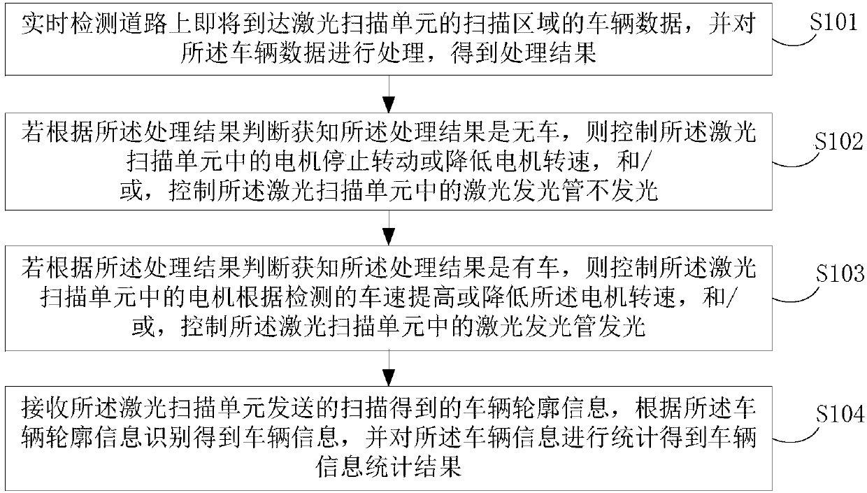
[0048] figure 1 A schematic flow chart of a laser vehicle detection method provided in this embodiment is shown, including:

[0049] S101. Real-time detection of vehicle data on the road that is about to arrive at the scanning area of ​​the laser scanning unit, and processing the vehicle data to obtain a processing result;

[0050] Wherein, the processing result includes whether there is a car or no car in the preset area;

[0051] The preset area is the road surface area between the detection area and the scanning area.

[0052] The processing result includes the vehicle speed when there are vehicles in the preset area.

[0053] Specifically, the detection functi...


PUM


Abstract

An embodiment of the invention discloses a laser type vehicle detecting method and a device thereof. The method comprises the steps of detecting vehicle data of the scanning area of a to-be-arrived laser scanning unit on a road, and performing processing for obtaining a processing result; and if no vehicle exists, stopping rotation of a motor or reducing rotating speed of the motor, and making a laser emitting tube stop laser emitting; and if the vehicle exists, increasing or reducing the rotation speed of the motor according to the detected vehicle speed, making the laser emitting tube emit laser; obtaining the vehicle information through identification according to vehicle contour information, and performing statistics for obtaining a vehicle information statistics result. According to the laser type vehicle detecting method and the device thereof, through stopping rotation of the motor or reducing the rotation speed of the motor and making the laser emitting tube do not emit laser when no vehicle is determined, and increasing or reducing the rotation speed of the motor and making the laser emitting tube emit laser when existence of the vehicle is determined, the working state ofthe motor and the laser emitting tube can be reasonably controlled according to the actual condition of the road, thereby prolonging service life of the motor and the laser emitting tube, and reducing maintenance cost and equipment purchasing cost.

Description

technical field [0001] Embodiments of the present invention relate to the technical field of intelligent transportation, and in particular to a laser vehicle detection method and device. Background technique [0002] In recent years, with the rapid development of scanning laser ranging technology, it has been widely used in the field of intelligent transportation. With its high-precision measurement, especially in the investigation of traffic conditions, it has shown significant advantages and is increasingly trusted by customers. The scanning laser ranging sensor is a high-precision, high-tech precision product. Its application environment in the field of traffic situation investigation is relatively complicated. In most of the time, there are no vehicles passing through the detection area on the road, but the scanning laser ranging sensor The motor and laser light-emitting tube in the sensor are always in working condition. Continuous work for a long time will inevitably r...

Claims


Application Information

Patent Timeline
Patent Type & Authority Applications(China)
IPC IPC(8): G08G1/04
Inventor 杨勇刚胡攀攀李康
Owner WUHAN WANJI INFORMATION TECH
Learn More