Processing and measuring method of high angular accuracy infrared optical parts

A measuring method and technology of optical parts, applied in the field of optical parts processing

Active Publication Date: 2018-01-30
TIANJIN JINHANG INST OF TECH PHYSICS
View PDF4 Cites 12 Cited by
  • Summary
  • Abstract
  • Description
  • Claims
  • Application Information

AI Technical Summary

Problems solved by technology

[0004] The purpose of the present invention is to propose a processing and measuring method for high angular precision infrared optical parts to solve the technical problem of how to prepare high angular precision infrared optical parts

Method used


Image

  • Processing and measuring method of high angular accuracy infrared optical parts
  • Processing and measuring method of high angular accuracy infrared optical parts
  • Processing and measuring method of high angular accuracy infrared optical parts

Examples


Embodiment Construction

[0023] In order to make the purpose, content, and advantages of the present invention clearer, the specific implementation manners of the present invention will be further described in detail below in conjunction with the accompanying drawings and embodiments.

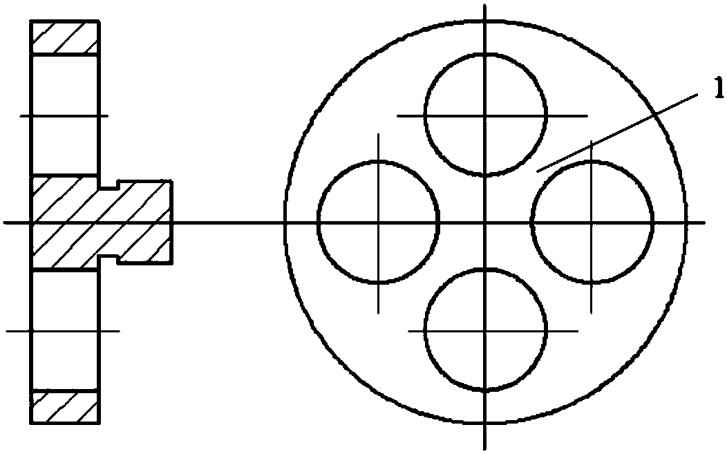
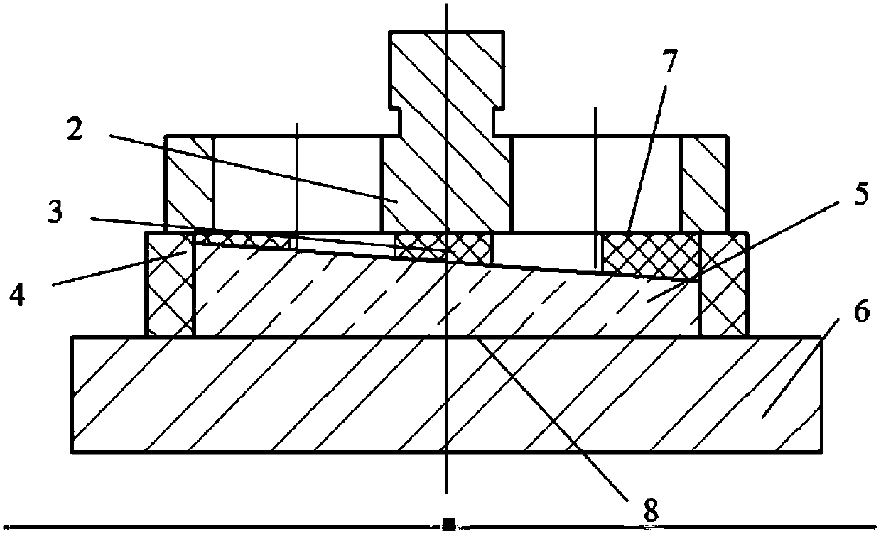
[0024] This embodiment proposes a processing and measuring method for a high-angular-precision infrared wedge prism. The processing and measuring method includes blanking, rough grinding, fine grinding, polishing, and inclination grinding in sequence; There is no special process except for controlling the size of the external margin.

[0025] Fine grinding specifically includes: fine grinding a straight face of the wedge prism as a reference plane, processing it to aperture N=2; and then fine grinding the slope opposite to the straight face by controlling the thickness difference until the thickness difference reaches the theoretically calculated value.

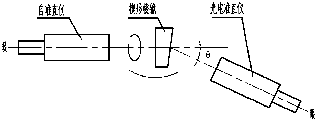
[0026] The high-precision wedge angle of ±1″ of the wedge prism ...


PUM


Abstract

The invention belongs to the technical filed of processing of optical parts, and particularly relates to a processing and measuring method of high angular accuracy infrared optical parts. According tothe method, when the optical parts are arranged on trays, a bonding disk which is provided with multiple light penetrating reflection holes is adopted, and through reflection images of the light penetrating reflection holes, plane states of planes to be polished of the optical parts can be expressed overall; in the polishing process, an automatic collimator, a photoelectric collimator and a standard angle gauge block are used for measuring the polishing accuracy of the wedge angle of a wedge-shaped prism, and the infrared wedge-shaped prism with high angular accuracy can be prepared.

Description

technical field [0001] The invention belongs to the technical field of optical parts processing, and in particular relates to a method for processing and measuring infrared optical parts with high angular precision. Background technique [0002] The infrared wedge prism is an infrared deflection device with second-level precision, and it is a key device used in the scanning mechanism of the infrared optical system. Compared with other scanning methods, the infrared optical system scanning mechanism using infrared deflection device has many advantages such as high scanning efficiency, stable movement and compact structure. However, this method has high requirements on various indicators such as the processing requirements for the angular precision of the infrared deflection device that is not transparent to visible light, so its application is limited. Therefore, it is necessary to propose a processing method suitable for infrared optical parts with high angular precision, a...

Claims


Application Information

Patent Timeline
Patent Type & Authority Applications(China)
IPC IPC(8): B24B13/00B24B13/005B24B9/14B24B49/12G01B11/26G01B11/30
Inventor 回长顺沈羿
Owner TIANJIN JINHANG INST OF TECH PHYSICS
Why Eureka
Try Eureka