Transfer device

A technology of transferring device and processing position, applied in the direction of conveyor objects, transportation and packaging, etc., can solve the problems of large occupied space and complex structure.

Inactive Publication Date: 2018-01-30
GUANGDONG TIANJI IND INTELLIGENT SYST CO LTD
View PDF5 Cites 9 Cited by
  • Summary
  • Abstract
  • Description
  • Claims
  • Application Information

AI Technical Summary

Problems solved by technology

However, due to its relatively complex structure, the traditional transfer device occupies a relatively large space, so it cannot meet the actual needs of automated production and processing.

Method used


Image

  • Transfer device
  • Transfer device
  • Transfer device

Examples


Embodiment Construction

[0025] In order to facilitate understanding of the present invention, the present invention will be described more fully hereinafter with reference to the related drawings. The preferred embodiments of the invention are shown in the accompanying drawings. However, the present invention may be embodied in many different forms and is not limited to the embodiments described herein. Rather, these embodiments are provided so that a thorough and complete understanding of the present disclosure is provided.

[0026] It should be noted that when an element is referred to as being "fixed to" another element, it can be directly on the other element or intervening elements may also be present. When an element is referred to as being "connected" to another element, it can be directly connected to the other element or intervening elements may also be present. The terms "vertical", "horizontal", "left", "right" and similar expressions used herein are for the purpose of illustration only ...


PUM


Abstract

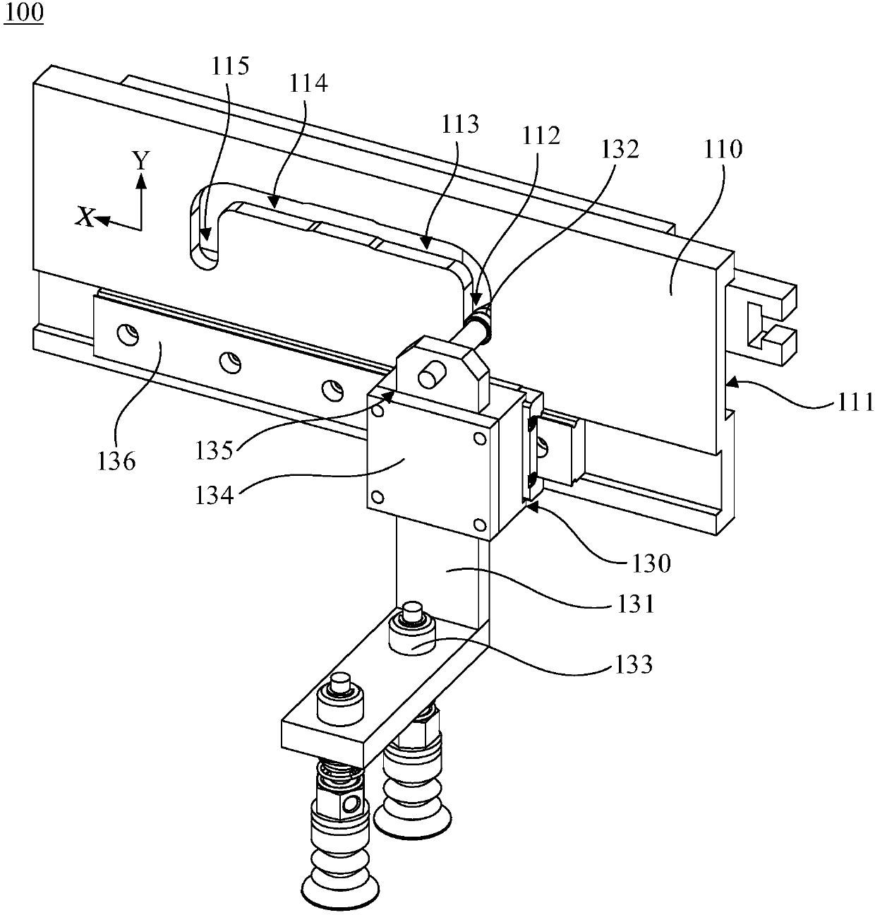
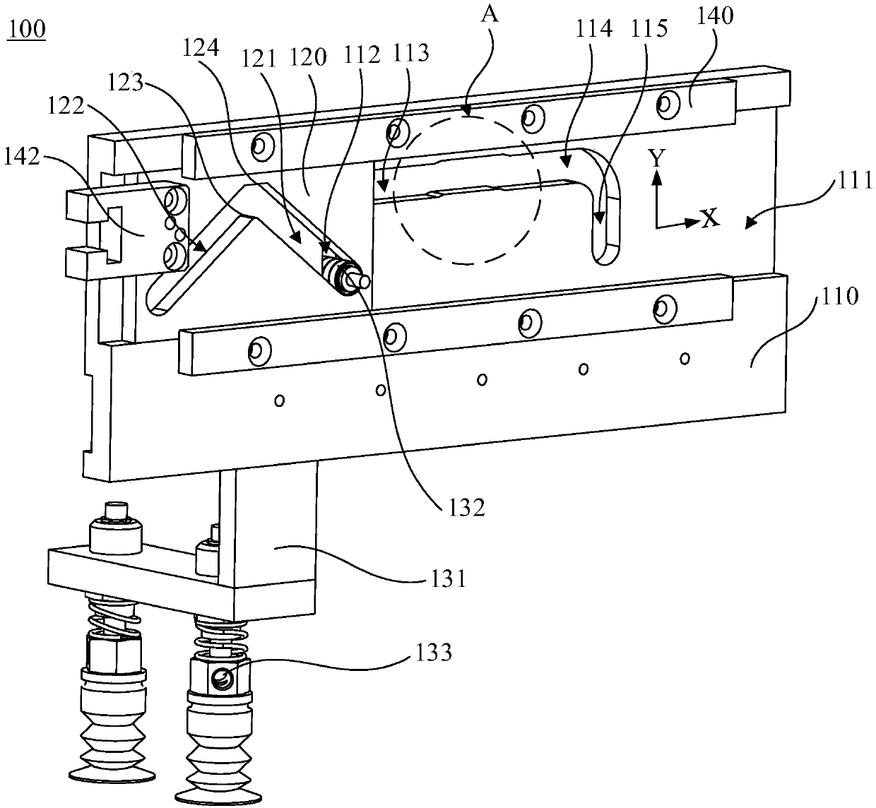
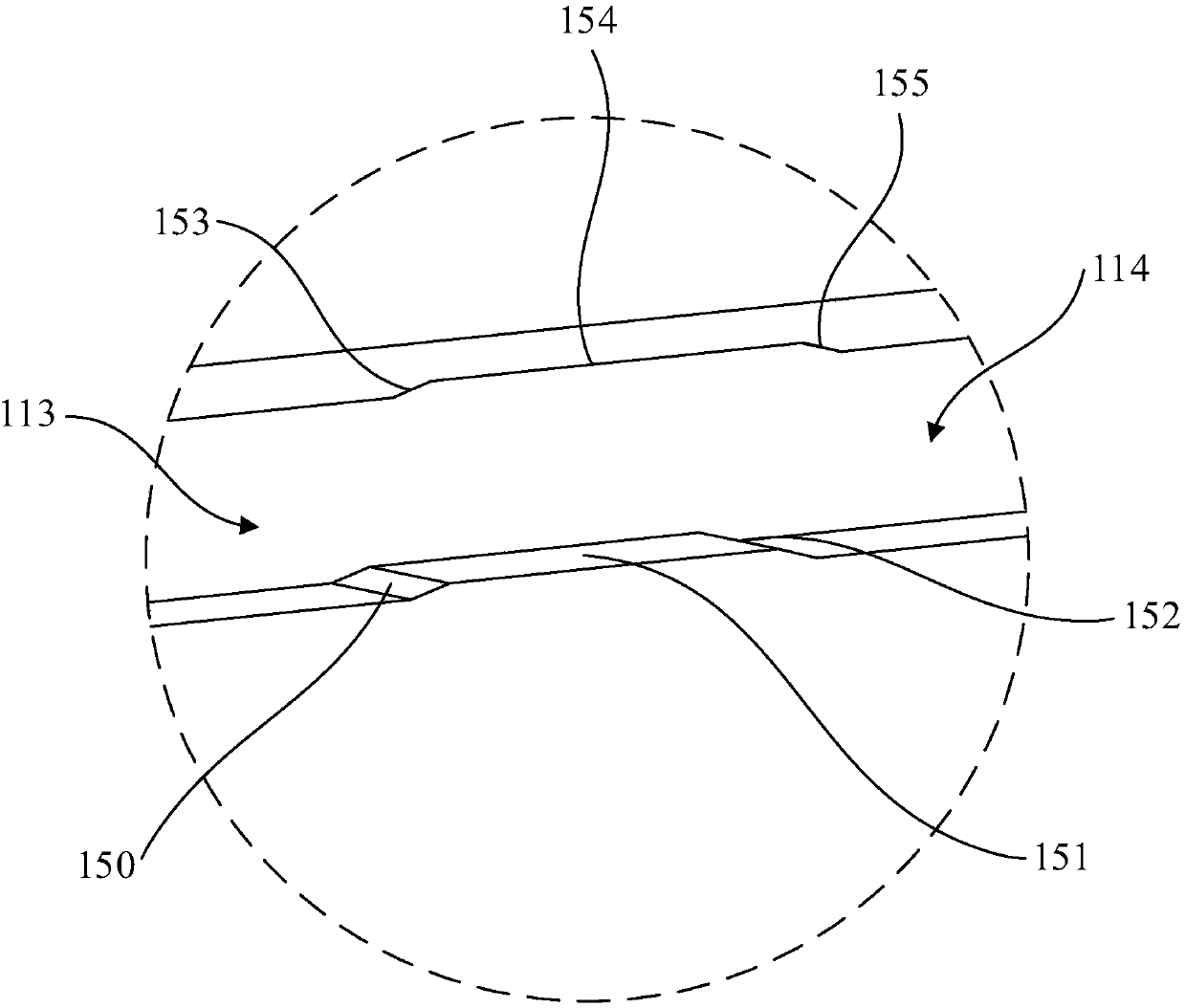
The invention relates to a transfer device which is used for transferring a workpiece to a machining position. The transfer device includes a base, a sliding block and a feeding mechanism, wherein oneside of the base is provided with a sliding groove and a first guide groove which are communicated with each other; the sliding block is slidably arranged in the sliding groove and provided with a first chute; and the feeding mechanism includes a first connecting piece, a cam and a sucker. The first connecting piece is slidably arranged on the other side of the base, the cam is connected with oneside of the first connecting piece and slidably abuts in the first chute and the first guide groove, and the sucker is arranged on the other side of the first connecting piece and used for taking andplacing the workpiece. When the sliding block moves in the first direction in the sliding groove, one inner side wall of the first chute abuts against the cam, so that the cam moves in the second direction in the first guide groove, the first connecting piece moves in the second direction relative to the base, and the sucker transfers the workpiece to the machining position. The transfer device implements complex motions through the simple mechanical structure, an occupied space is reduced, and the production line cost is reduced.

Description

technical field [0001] The invention relates to the field of automatic processing equipment, in particular to a transfer device. Background technique [0002] In the current automated assembly process of electronic components and connector products, the speed and stability of automatic workpiece transfer are particularly important. By using a transfer device to pick up and transport workpieces that need to be displaced on the production line instead of manual operations to achieve Mechanization and automation of production. However, the traditional transfer device occupies a relatively large space due to its relatively complex structure, so it cannot meet the actual needs of automated production and processing. SUMMARY OF THE INVENTION [0003] Based on this, it is necessary to provide a transfer device with a simple structure and a small footprint. [0004] A transfer device for transferring a workpiece to a processing position, comprising: [0005] a base, one side of...

Claims


Application Information

Patent Timeline
Patent Type & Authority Applications(China)
IPC IPC(8): B65G47/91
Inventor 陈勇军
Owner GUANGDONG TIANJI IND INTELLIGENT SYST CO LTD
Why Eureka
Try Eureka