
Pile hole casting adjustment structure

A technology for adjusting structure and pile holes, applied in the direction of infrastructure engineering, construction, etc., can solve the problems of slow construction progress, difficult control of pile top elevation, affecting the original facilities of engineering piles, etc., to improve the stability of movement and provide grouting. effect of effect

Active Publication Date: 2018-01-30
CHINA MCC5 GROUP CORP
View PDF2 Cites 4 Cited by
  • Summary
  • Abstract
  • Description
  • Claims
  • Application Information

AI Technical Summary

Problems solved by technology

[0002] At present, the construction methods of prefabricated concrete piles basically adopt the hammering method and the static pressure method. The main defects of these two methods of pile driving are: to produce a soil squeezing effect, which will affect the engineering pile and the surrounding original facilities; It is difficult to control, and the integrity of the pile body cannot be guaranteed; the vibration and noise generated by the hammering method will affect the surrounding environment. Therefore, there are many disadvantages in the pile sinking construction using the hammering method or the static pressure method
However, this method needs to pour concrete slurry into the mud hole to form a mixed slurry before sinking the pile. The discharge volume of the mixed slurry is the actual volume of the prefabricated concrete pile or concrete pipe pile, and the discharged mixed slurry contains concrete slurry, resulting in waste, while affecting the environment, and the overall construction progress is slow

Method used


Image

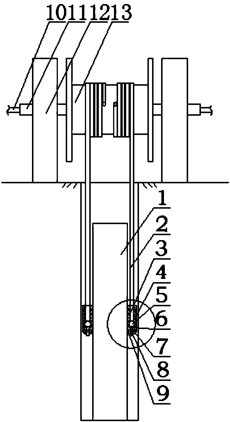
  • Pile hole casting adjustment structure
  • Pile hole casting adjustment structure
  • Pile hole casting adjustment structure

Examples


Embodiment 1

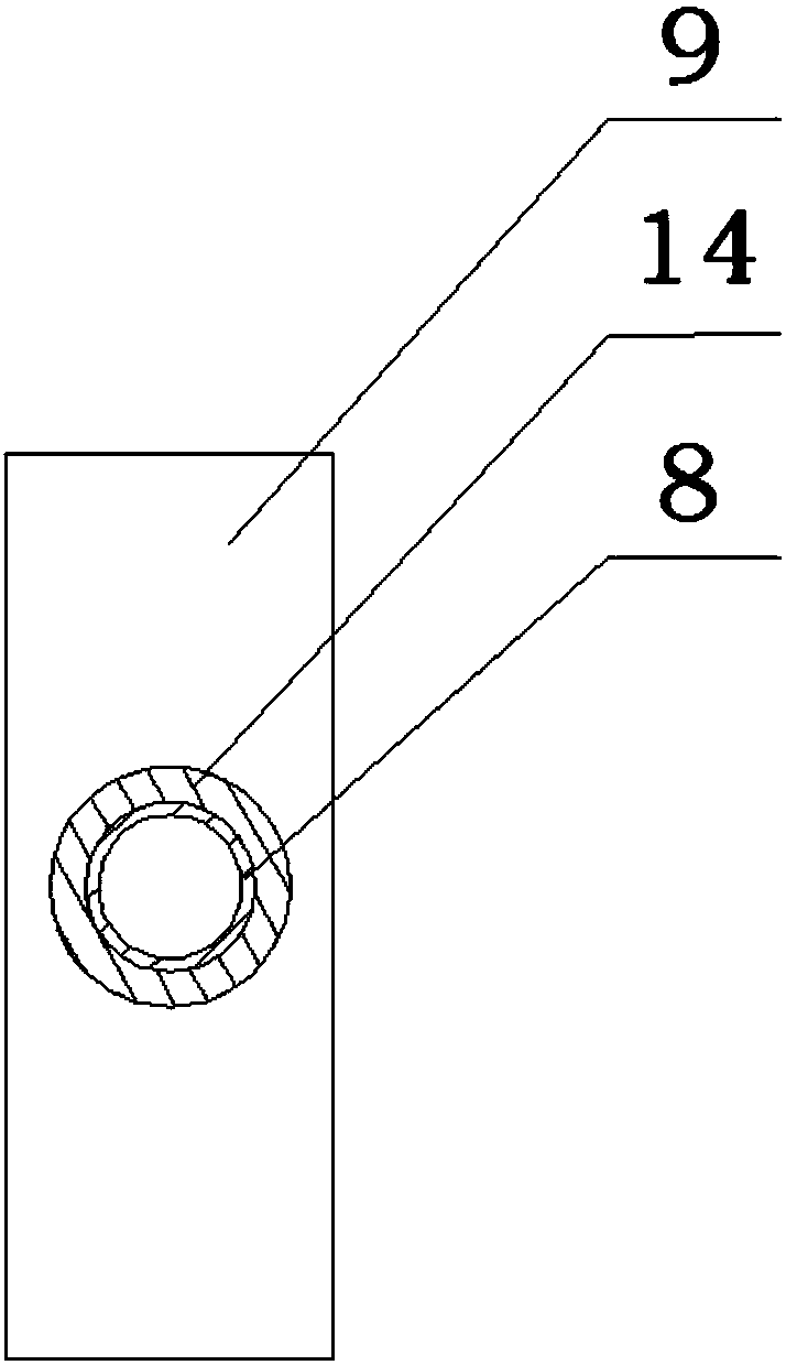
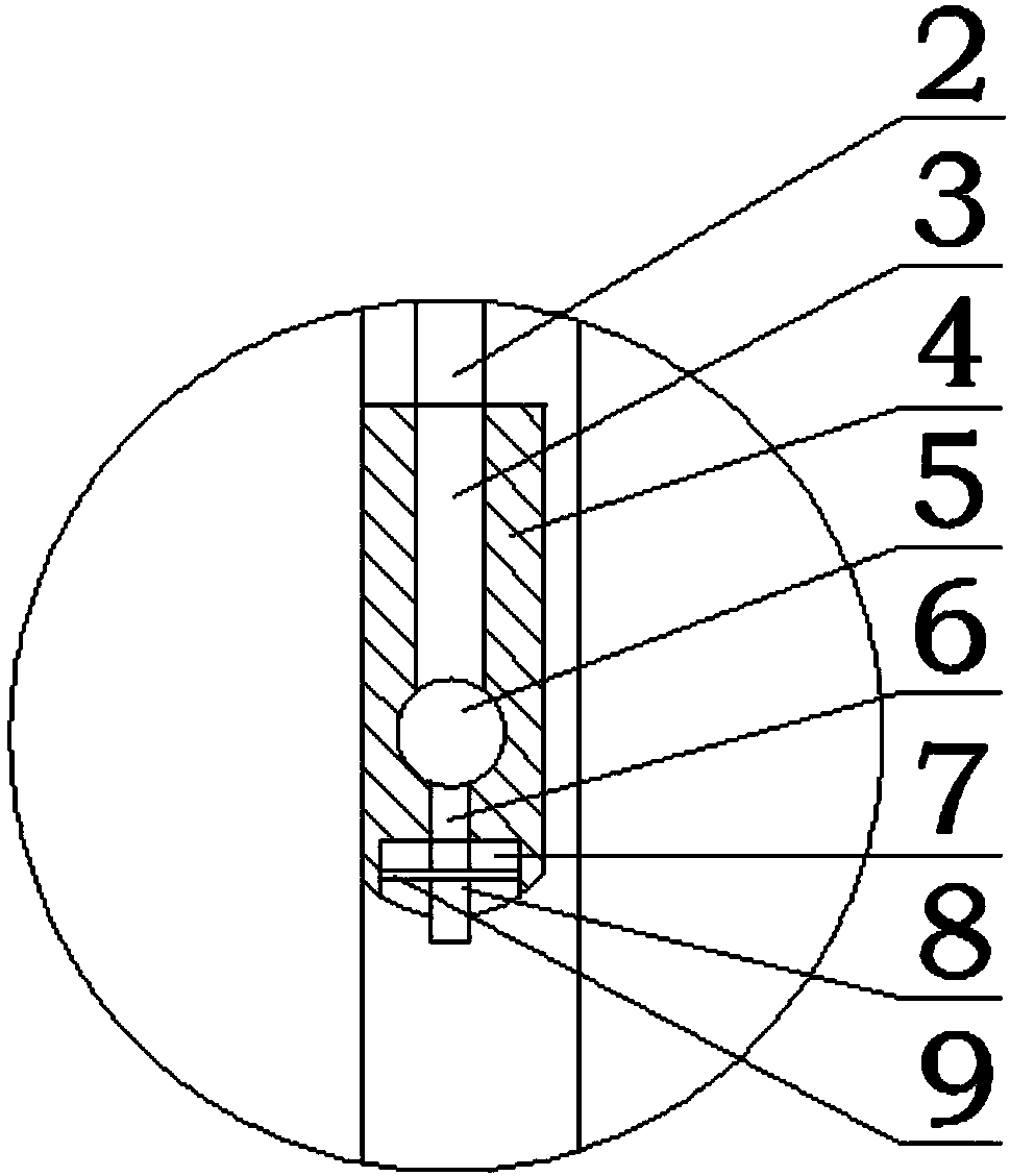
[0024] Such as Figure 1~3As shown, this embodiment includes a roller 13 and two mutually parallel columns 12, and the two ends of the roller 13 are respectively rotated through the rotating shaft 11 and installed on the two columns 12, along the axis of each rotating shaft 11 A flow channel is opened inside it, and the feed pipe 10 communicates with the flow channel, and a cavity communicated with the flow channel is provided inside the roller 13, and two small holes are opened on the outer peripheral wall of the roller 13, each A grouting pipe 2 is connected to each of the small holes, and the end of the grouting pipe 2 extends in the pile hole after being evenly wound on the outer wall of the roller 13 along the circumferential direction of the roller 13; An annular grouting head 4 whose outer diameter matches that of the pile 1 is provided with an annular buffer cavity 5 inside along the circumference of the grouting head 4 , and there are two buffer chambers on the upper ...

Embodiment 2

[0029] Such as Figure 1~3 As shown, in this embodiment, the longitudinal section of the buffer cavity 5 is circular. The longitudinal section of the buffer chamber 5 is circular, so that the concrete slurry entering from the two grouting holes 3 can quickly fill the entire buffer chamber 5, so as to quickly realize multiple diversions on the bottom surface of the grouting head 4, and in the After the grouting is completed, the grouting pipe 2 and the grouting head 4 need to be cleaned, and the circular inner wall of the buffer chamber 5 is not easy to attach residual concrete grout, so as to facilitate the smooth passage of the concrete grout during the next pile hole grouting .

[0030] As preferably, since the pile hole and the concrete pile 1 are all cylindrical, that is, when the grouting process is carried out to the annular space between the pile hole and the concrete pile 1, a plurality of grooves 9 are located at the circumference of the lower end surface of the grou...


PUM


Abstract

The invention discloses a pile hole casting adjustment structure which comprises a roller and two columns. A feeding pipe is communicated with a flow way, a cavity communicated with the flow way is formed in the roller, two small holes are formed in the outer circumferential wall of the roller, and each small hole is connected with a casting pipe. A buffer cavity is formed in a casting head in theperipheral direction of the casting head, two casting holes are formed in the upper surface of the casting head and are connected with the casting pipes, multiple grooves are formed in the lower surfaces of the casting holes, through holes are formed in the bottoms of the grooves, partition plates are fixed to the walls of the grooves, universal balls are arranged on the partition plates, the upper ends of adjusting pipes penetrate through the middles of the universal balls, and two ends of a hose are connected with the bottom of the buffer cavity and the upper ends of the adjusting pipes. After a concrete pile sinks, concrete grout is injected into a pile hole, excessive concrete grout is extruded out of the pile hole, concrete grout waste is avoided, and meanwhile overflowing concrete grout is prevented from polluting the environment or a construction period is prevented from being prolonged.

Description

technical field [0001] The invention relates to the field of building construction, in particular to a pile hole grouting adjustment structure. Background technique [0002] At present, the construction methods of prefabricated concrete piles basically adopt the hammering method and the static pressure method. The main defects of these two methods of pile driving are: to produce a soil squeezing effect, which will affect the engineering pile and the surrounding original facilities; It is difficult to control, and the integrity of the pile body cannot be guaranteed; the vibration and noise generated by the hammering method will affect the surrounding environment. Therefore, there are many disadvantages in the pile sinking construction using the hammering method or the static pressure method. The rooted pile is drilled with a drilling rig, the soil in the hole is stirred into mud, and the concrete slurry is injected into the mud hole to make a mud hole larger than the pile dia...

Claims


Application Information

Patent Timeline
Patent Type & Authority Applications(China)
IPC IPC(8): E02D15/04
Inventor 罗建勋罗利罗刚
Owner CHINA MCC5 GROUP CORP
Learn More