A kind of transmission structure for syringe and syringe

A transmission structure and syringe technology, applied in the field of medical devices, can solve the problems of unclear hand feel, inability to meet the high quality and high experience of user life, poor subjective feeling, etc., to reduce the type of motion connection, crisp rotating sound, and texture. Pause effect

Active Publication Date: 2022-02-15
SUNSHINE LAKE PHARM CO LTD
View PDF10 Cites 0 Cited by
  • Summary
  • Abstract
  • Description
  • Claims
  • Application Information

AI Technical Summary

Problems solved by technology

Therefore, the use of convenient and reliable syringes is becoming more and more popular. However, there are syringes on the market, such as insulin pens, which give users unclear hand feeling and poor subjective experience in the process of adjusting doses, and cannot meet the high expectations of users for life. Demand for quality and high experience

Method used


Image

  • A kind of transmission structure for syringe and syringe
  • A kind of transmission structure for syringe and syringe
  • A kind of transmission structure for syringe and syringe

Examples


Embodiment 1

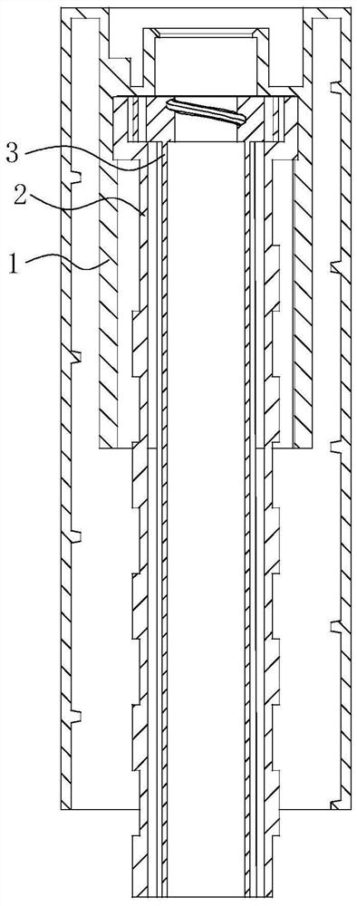
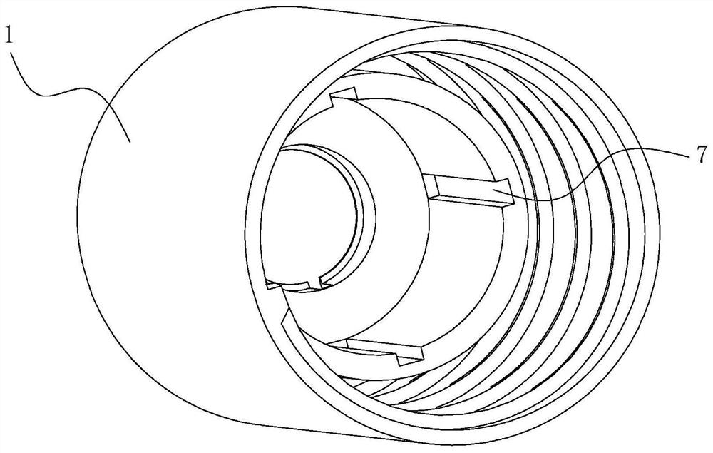
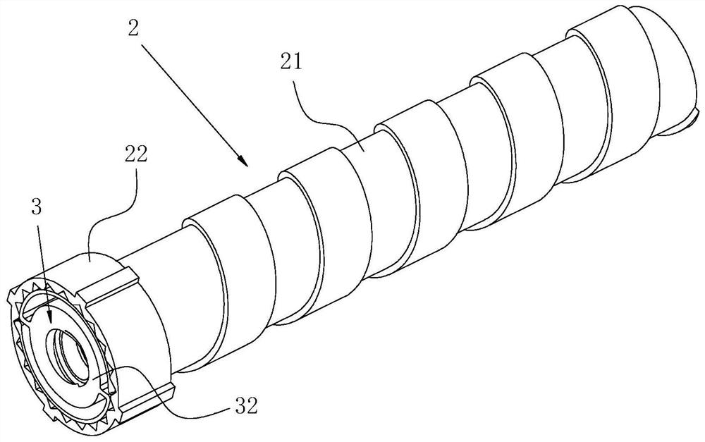
[0081] A transmission structure for a syringe, such as figure 1 As shown, it includes: an installation shell 1, a cavity is provided inside the installation shell 1; a composite sleeve, the composite sleeve includes an external sleeve 2 and an internal sleeve 3, and the external sleeve 2 is sleeved on the outside of the built-in sleeve 3, the external sleeve 2 is rotatably connected to the built-in sleeve 3, the composite sleeve is installed inside the installation shell 1, and the composite sleeve The barrel is slidably connected with said mounting housing 1 only in the axial direction.

[0082] Specifically, during the specific use of the transmission structure, the installation housing 1 is stationary, the outer sleeve 2 moves linearly along its axial direction, and the inner sleeve 3 moves linearly along its axial direction. While moving, it rotates along its axis. If the built-in sleeve 3 is in direct contact with the installation shell 1 and has a kinematic connection ...

Embodiment 2

[0085] The difference between this embodiment and Embodiment 1 is:

[0086] In this embodiment, the built-in sleeve includes a built-in long tube and a connector arranged on the built-in long tube, and the external sleeve includes an outer long tube and a connector set on the outer long tube A cap, the connecting head is embedded in the cap. The outer diameter of the connecting head is larger than the outer diameter of the built-in long pipe, the outer diameter of the cap is larger than the outer diameter of the outer long pipe, and the connecting head is arranged at the axial end of the built-in long pipe , the cap is arranged on the axial end of the external long tube. By arranging the cap to cover the outer side of the connecting head, the connecting head and the mounting shell are spaced apart from each other, so as to avoid the kinematic connection between the connecting head and the mounting shell, thereby realizing the connection between the moving parts. The simplifi...

Embodiment 3

[0090] The difference between this embodiment and Embodiment 1 is:

[0091] The outer wall of the cap is provided with a third connecting piece, the inner wall of the installation housing is provided with a fourth connecting piece, and the third connecting piece is slidably connected with the fourth connecting piece in the axial direction. The third connecting piece and the fourth connecting piece are used to limit the relative rotation between the cap and the mounting case, and guide the axial sliding between the cap and the mounting case effect.

[0092] In this embodiment, the third connecting piece is four sliding blocks, the fourth connecting piece is four sliding slots, the sliding slots are extended along the axial direction of the installation housing, and the sliding slots The block fits snugly in said chute. The cross-sectional shape of the slider is rectangular, and the cross-sectional shape of the notch of the chute is the same as the cross-sectional shape of the...


PUM


Abstract

The invention belongs to the technical field of medical devices, and discloses a transmission structure for a syringe, comprising a mounting shell, a cavity is arranged inside the mounting shell; a composite sleeve, the composite sleeve includes an external sleeve and a built-in sleeve sleeve, the outer sleeve is set on the outside of the inner sleeve, the outer sleeve is rotatably connected with the inner sleeve, and the composite sleeve is installed inside the installation shell, so The composite sleeve is slidably connected with the installation shell in the axial direction. The invention also discloses a syringe with the above-mentioned transmission structure. The present invention reduces the type of kinematic connection between the transmission parts, so that there is only one mutual motion relationship between the parts, so that the transmission structure is more reliable, and the syringe can provide users with a more textured sense of pause and a more crisp rotation sound.

Description

technical field [0001] The invention relates to the technical field of medical devices, in particular to a transmission structure for a syringe and a syringe. Background technique [0002] With the development of society, changes in people's living habits, excessive work pressure, and changes in diet structure, more and more people suffer from long-term diseases and need long-term injections of drugs to maintain their health, and patients with these diseases appear young trend. Therefore, the use of convenient and reliable syringes is becoming more and more popular. However, there are syringes on the market, such as insulin pens, which give users unclear hand feeling and poor subjective experience in the process of adjusting doses, and cannot meet the high expectations of users for life. Demand for quality and high experience. [0003] Based on the above situation, it is necessary for us to design a syringe to solve the above problems and improve the user experience. Con...

Claims


Application Information

Patent Timeline
Patent Type & Authority Patents(China)
IPC IPC(8): A61M5/31A61M5/178
CPCA61M5/178A61M5/31A61M5/3129
Inventor 李润庞任维朱波陈小锋李文佳
Owner SUNSHINE LAKE PHARM CO LTD
Why Eureka
Try Eureka