Track type shot blasting machine

A shot blasting machine, orbital technology, applied in abrasive jet machine tools, used abrasive treatment devices, abrasives, etc., can solve the problem of poor practicability, reduced work efficiency, and a lot of time to install and remove mechanical parts, etc. problem, to achieve the effect of strong practicability, improve work efficiency, and facilitate shot blasting

Inactive Publication Date: 2018-02-02
袁月
View PDF0 Cites 5 Cited by
  • Summary
  • Abstract
  • Description
  • Claims
  • Application Information

AI Technical Summary

Problems solved by technology

[0002] The shot blasting machine uses the high-speed rotating impeller to throw the projectiles to the workpieces that are continuously turned in the drum, so as to achieve the purpose of cleaning the workpieces. It is suitable for sand cleaning, rust removal, and descaling of castings and forgings below 15 kg in various industries. Scale and surface strengthening, the existing shot blasting machine is used to clean the mechanical parts, usually the mechanical parts are fixed first, then the mechanical parts are elastically tightened in the shot blasting chamber, and then shot blasting, and finally the mechanical parts are taken out and cleaned. Replace, and then repeat the above steps. When the existing shot blasting machine performs shot blasting, it takes a lot of time to install and disassemble the mechanical parts, which reduces the work efficiency and is not practical.

Method used


Image

  • Track type shot blasting machine
  • Track type shot blasting machine
  • Track type shot blasting machine

Examples


Embodiment Construction

[0019] The following will clearly and completely describe the technical solutions in the embodiments of the present invention with reference to the accompanying drawings in the embodiments of the present invention. Obviously, the described embodiments are only some, not all, embodiments of the present invention. Based on the embodiments of the present invention, all other embodiments obtained by persons of ordinary skill in the art without making creative efforts belong to the protection scope of the present invention.

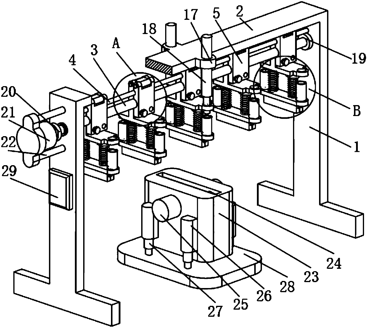
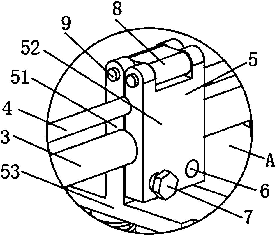
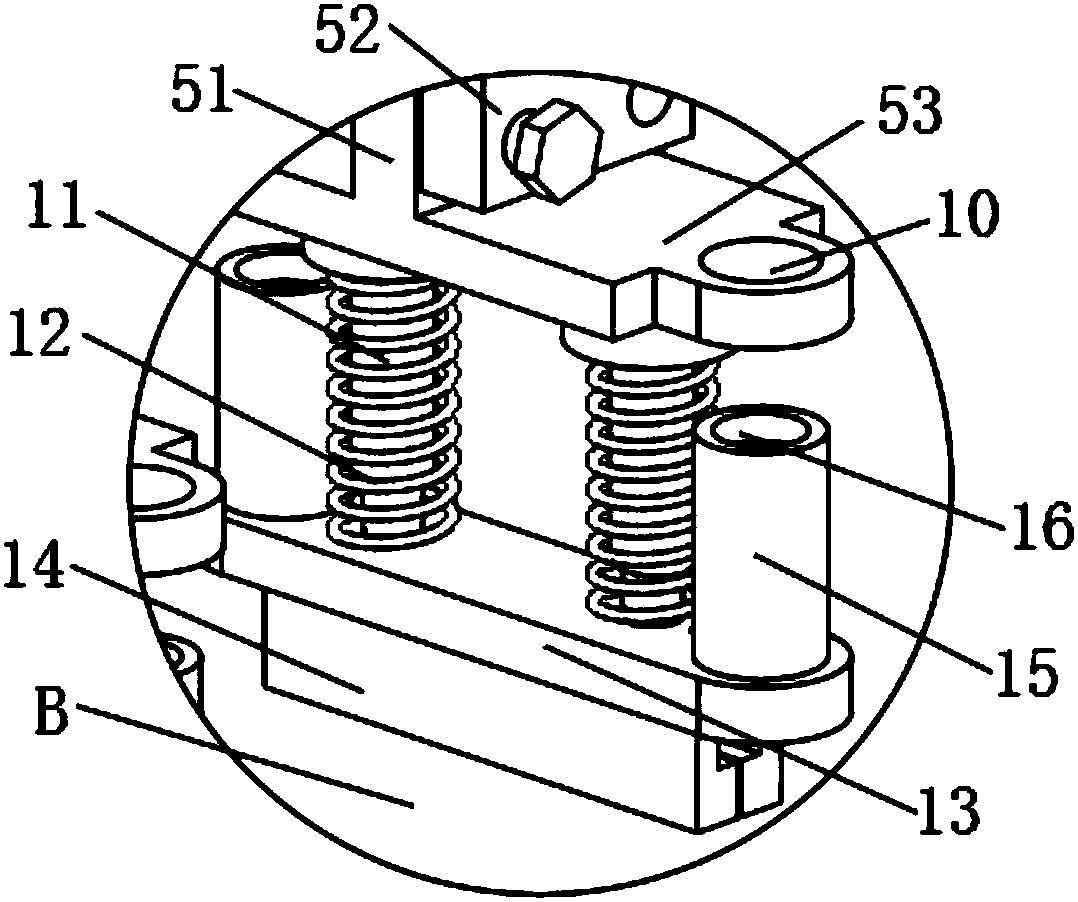
[0020] see Figure 1-3, the present invention provides a technical solution: a track-type shot blasting machine, including a mounting plate 2, the lower surface of the mounting plate 2 is provided with two symmetrically arranged support rods 1, which play the role of supporting the mounting plate 2, and the support rods 1 is provided with a PLC controller 29 in the middle of the side surface, a guide rod 4 and a screw rod 3 are provided on the inner surface of...


PUM


Abstract

The invention discloses a rail-type shot blasting cleaning machine, which comprises a mounting plate, two symmetrically arranged support rods are arranged on the lower surface of the mounting plate, a PLC controller is provided in the middle of the side of the support rods, and a PLC controller is arranged on the inner surface of the support rods. The upper end is provided with a guide rod and a screw rod. The guide rod is located on the upper side of the screw rod. The left end of the screw rod is fixedly connected with the output shaft of the stepper motor through a coupling. The stepper motor is fixedly connected with the support rod through the mounting seat. As for the clip, the lower end of the clip is provided with two symmetrically arranged telescopic rods, and the fixed end of the telescopic rod is fixedly connected with the fixed plate of the clip. The track-type shot blasting machine can quickly disassemble and install the clips, and can fix multiple workpieces at the same time, saving time and improving work efficiency, and the first electric telescopic rod can push the support plate to move down, and the second The electric telescopic rod can push the cleaning barrel to move upwards, which is convenient for shot blasting of workpieces and has strong practicability.

Description

technical field [0001] The invention relates to the technical field of surface treatment of mechanical parts, in particular to an orbital shot blasting machine. Background technique [0002] The shot blasting machine uses the high-speed rotating impeller to throw the projectiles to the workpieces that are continuously turned in the drum, so as to achieve the purpose of cleaning the workpieces. It is suitable for sand cleaning, rust removal, and descaling of castings and forgings below 15 kg in various industries. Scale and surface strengthening, the existing shot blasting machine is used to clean the mechanical parts, usually the mechanical parts are fixed first, then the mechanical parts are elastically tightened in the shot blasting chamber, and then shot blasting, and finally the mechanical parts are taken out and cleaned. Replace, and then repeat the above steps, when the existing shot blasting machine performs shot blasting, it takes a lot of time to install and disasse...

Claims


Application Information

Patent Timeline
IPC IPC(8): B24C1/08B24C9/00B24C3/04
CPCB24C1/086B24C3/04B24C9/00
Inventor 袁月
Owner 袁月
Why Eureka
Try Eureka