Wood bending machine preventing wood deformation

A technology of wood deformation and wood, which is applied in the field of wood bending equipment, can solve the problems of high stamping force, easy deformation and damage, large stamping force, wood deformation and damage, etc., and achieve reliable effect of bending wood

Active Publication Date: 2018-02-02
重庆市浩源门业有限公司
View PDF5 Cites 1 Cited by
  • Summary
  • Abstract
  • Description
  • Claims
  • Application Information

AI Technical Summary

Problems solved by technology

[0004] The above technical scheme is used to realize the bending of wood. Since there is no buffer to provide buffer force for the punching force, the force provided by the oil cylinder is almost all on the wood, and the punching force on the wood is large, which is not good for the bending of the wood. It is easy to cause deformation and damage to the wood, so the above-mentioned technical solution still does not solve the problem that the wood is easily deformed and damaged due to the high stamping force in the process of wood bending and forming

Method used


Image

  • Wood bending machine preventing wood deformation
  • Wood bending machine preventing wood deformation
  • Wood bending machine preventing wood deformation

Examples


Embodiment 1

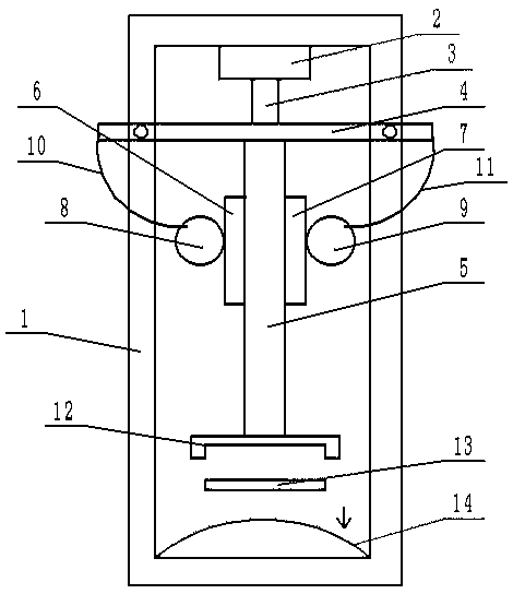
[0027] Such as figure 1 As shown, a wood bending machine for preventing wood deformation, the frame 1 is a rectangular frame, and a mold 14 is placed at the bottom of the rectangular frame, and the upper surface of the mold 14 is a curved surface. A hydraulic cylinder 2 is installed at the frame top of the rectangular frame, the cylinder body of the hydraulic cylinder 2 is connected with the rectangular frame by bolts, and the output shaft 3 of the hydraulic cylinder is vertically downward. The rectangular frame is welded below the hydraulic cylinder 2 with a horizontal bearing plate 4, which deforms when the bearing plate 4 is stressed. The material of the bearing plate 4 is preferably manganese steel plate, and the output shaft 3 of the hydraulic cylinder is perpendicular to the bearing plate 4. , the output shaft of the hydraulic cylinder is in contact with the upper surface of the bearing plate 4 when extending out. The lower surface of the bearing plate 4 is welded to th...

Embodiment 2

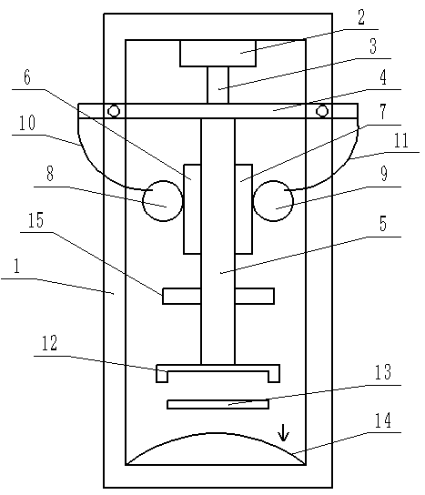
[0034] The difference between embodiment 2 and embodiment 1 is that embodiment 2 adds a steam box 15 and a steam hole 16 is opened on the clamping part 12 . Such as image 3As shown, the steam box 15 is installed symmetrically along both sides of the support rod 5 shaft, and water vapor can be sprayed out from the bottom of the steam box 15, and the steam box 15 is provided with an induction switch for controlling the spraying of water vapor. Such as Figure 5 As shown, the clamping member 12 is provided with steam holes 16 for spraying water steam, and the steam holes 16 are preferably evenly distributed.

[0035] In specific implementation, such as Figure 4 As shown, the steam source is provided by the steam box 15, and the induction switch on the steam box 15 can sense the rotation of the first gear 8 and the second gear 9. When the first gear 8 and the second gear 9 rotate, the induction switch controls Water vapor is sprayed out from the bottom of the steam box 15, an...


PUM


Abstract

The invention relates to the field of wood bending equipment and in particular to a wood bending machine preventing wood deformation. The wood bending machine includes a rack. The top of the rack is provided with a hydraulic cylinder and the bottom of the rack is provided with a mould. The rack is provided with a loaded plate deformed under stress, a vertical supporting rod and a clamping elementused for clamping wood and deformed under stress from top to bottom. The loaded plate is fixed on the rack horizontally and is located below the hydraulic cylinder. The lower surface of the loaded plate is fixedly connected with the upper end of the supporting rod and the lower end of the supporting rod is connected with the clamping element in a detachable mode. The two sides of the supporting rod are fixedly provided with vertical gear strips symmetrically and the rack of the two sides of the supporting rod is connected with gear wheels in a rotation mode separately. Each gear wheel meshes with the gear strip in the same side with the corresponding gear wheel and both ends of the loaded plate are all connected with steel tendons. The steel tendons are fixed on the end surface of the gearwheels in the same side with the steel tendons too and the places for fixing are far away from the gear strips in the same side with the steel tendons at the same time. According to the technical scheme, stamping force on the wood can be buffered and the fact that the wood is deformed and damaged due to the high stamping force is avoided.

Description

technical field [0001] The invention relates to the field of wood bending equipment, in particular to a wood bending machine for preventing wood deformation. Background technique [0002] Wood bending is the furniture or other wood products that bend and deform solid wood into the desired shape under a specific process. The existing solid wood bending machine has a cumbersome structure, complicated operation, large volume, high production cost, and one piece of equipment can only produce products with the same length and curvature. The wood is easily damaged during the production process, and the quality of wood bending is unstable. . [0003] In order to solve the above problems, the Chinese patent with the publication number CN205438802U discloses a solid wood bending machine, comprising a frame, a load-bearing top plate is provided at the bottom of the frame, and a vertically arranged oil cylinder is provided below the force-bearing top plate. The top of the piston rod ...

Claims


Application Information

Patent Timeline
Patent Type & Authority Applications(China)
IPC IPC(8): B27H1/00
CPCB27H1/00
Inventor 陈晓瑜
Owner 重庆市浩源门业有限公司
Why Eureka
Try Eureka