Manipulating device of retractable bow rudder

A control device, retractable technology, used in transportation and packaging, ships, special-purpose ships, etc., can solve the problems of small effective space at the bow, lack of design experience, backward device research, etc., to achieve small clearance and improve maneuverability. , to meet the effect of operating requirements

Active Publication Date: 2018-02-02
BEIJING RES INST OF PRECISE MECHATRONICS CONTROLS
5 Cites 1 Cited by

AI-Extracted Technical Summary

Problems solved by technology

However, the bow rudder also has obvious defects. Due to the small effective space of the bow, the collapsible bow rudder is prone to conflict with other equipment in the arrangement.
Domestic research on the bow rudde...

Method used

In summary, the operating device of the retractable bow rudder of the present invention includes a set of steering gear and two sets of left and right symmetrical retractable rudder gears, the steering gear drives the rudder blades to swing, retracts The rudder device drives the rudder blades on both sides to retract and retract, and the multi-mechanism intersection design optimizes the relationship between the connecting rods and rocker arms of the mechanism in a limited space, optimizes the power consumption of each link, and improves the overall maneuverability of the underwater submersible.
Secondly, the retractable rudder device utilizes the arc guide rail form to realize the operation of retracting and retracting the rudder blades on both sides, which improves the support stiffness and ensures the stability of the rudder turning. Moreover, the arc-shaped guide rail associates the two actions...

Abstract

The invention discloses a manipulating device of a retractable bow rudder. The manipulating device comprises a steering device, a left rudder retracting device and a right rudder retracting device, the steering device comprises a steering engine, a steering rocker arm, a rotation shaft, a transition rocker arm, a connecting rod, a steering shaft rocker arm, a steering shaft, a left sliding seat, aleft arc-shaped guide rail, a right sliding seat and a right arc-shaped guide rail, and the steering engine is connected with the steering rocker arm. The transition rocker arm is connected with thesteering rocker arm through the rotation shaft. The two ends of the connecting rod are hinged to the transition rocker arm and the steering shaft rocker arm correspondingly, the steering shaft rockerarm is arranged in the middle of the steering shaft and fixedly connected with the steering shaft, and the left sliding seat and the right sliding seat are arranged at the two ends of the steering shaft correspondingly. The left arc-shaped guide rail and the right arc-shaped guide rail are symmetrically arranged, the left rudder retracting device and the right rudder retracting device are connected with the steering device through the left sliding seat and the right sliding seat correspondingly and can rotate by 90 degrees around the left arc-shaped guide rail and the right arc-shaped guide rail. By adoption of multi-mechanism intersection design, the relation of the connecting rod and the rocker arms of mechanisms is optimized in a limited space, and the overall manipulating performance of an underwater vehicle is improved.

Application Domain

Underwater vesselsUnderwater equipment

Technology Topic

Rocker armEngineering +2

Image

  • Manipulating device of retractable bow rudder
  • Manipulating device of retractable bow rudder

Examples

  • Experimental program(1)

Example Embodiment

[0044] In order to make the purpose, technical solution and advantages of the present invention clearer, the following will further describe the public implementation manners of the present invention in detail with reference to the accompanying drawings.
[0045] The retractable bow rudder control device described in the present invention is the first application on an underwater submersible. The advantages.
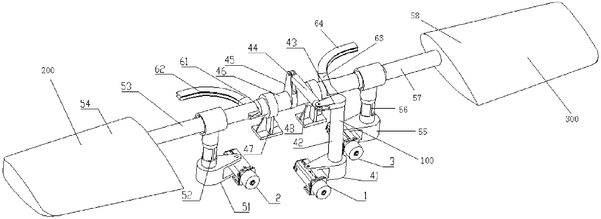
[0046] refer to figure 1 , shows a schematic structural view of a retractable bow rudder control device in an embodiment of the present invention. Among them, the X axis, Y axis and Z axis are defined: the direction where the rudder axis 46 is located is the direction where the X axis is located, the direction where the rotary axis 42 is located is the direction where the Z axis is located, and the direction where the axis of the rudder steering gear 1 is located is the direction where the Y axis is located .
[0047] like figure 1 , the control device of the retractable rudder includes: a steering device 100, a left retractable rudder device 200 and a right retractable rudder device 300; wherein, the left retractable rudder device 200 and the right retractable rudder device 300 are symmetrically arranged on the left and right sides of the steering device 100 .
[0048] In this embodiment, the rudder steering device 100 includes: a rudder steering gear 1, a rudder steering rocker 41, a rotary shaft 42, a transition rocker 43, a connecting rod 44, a rudder steering shaft rocker 45, a rudder steering shaft 46, left slide seat 61, left arc guide rail 62, right slide seat 63 and right arc guide rail 64.
[0049] in:
[0050]The steering steering gear 1 is connected to the steering rocker 41 .
[0051] The transition rocker arm 43 and the steering rocker arm 41 are arranged in parallel, and are connected by a rotary shaft 42 perpendicular to the plane where the transition rocker arm 43 and the steering rocker arm 41 are located. Preferably, the transitional rocker arm 43, the steering rocker arm 41 and the rotary shaft 42 can be located at the middle and upper part of the underwater vehicle; the three are fixedly connected by interference.
[0052] One end of the connecting rod 44 is hinged with the transition rocker 43 , and the other end is hinged with the steering shaft rocker 45 .
[0053] The steering shaft rocker 45 is arranged in the middle of the steering shaft 46 and is fixedly connected with the steering shaft 46; wherein, the steering shaft 46 passes through the central hole of the steering shaft rocker 45 ;
[0054] The left sliding seat 61 and the right sliding seat 63 are respectively arranged at two ends of the steering shaft 46 . Wherein, the left sliding seat 61 and the right sliding seat 63 mainly play the role of connection and torque transmission.
[0055] The left arc guide rail 62 and the right arc guide rail 64 are symmetrically arranged around the center of the steering shaft rocking arm 45; wherein, the left arc guide rail 62 is connected with the left slide seat 61; connect.
[0056] In this embodiment, the left retractable rudder device 200 is connected to the rudder steering device 100 through the left sliding seat 61; 90° rotation. The right retractable rudder device 300 is connected to the rudder steering device 100 through the right sliding seat 63 ; wherein, the right retractable rudder device 300 can rotate around the right arc-shaped guide rail 64 at 90°.
[0057] In a preferred embodiment of the present invention, the steering device 100 may further include: a left support 47 and a right support 48 . Wherein, the left support 47 and the right support 48 are symmetrically arranged around the center of the steering shaft rocker 45, and are fixedly connected with the steering shaft 46; wherein, the steering shaft 46 passes through the left The central holes of the support 47 and the right support 48 are used to support the steering device 100 .
[0058] In a preferred embodiment of the present invention, the steering gear 1 is connected to the pressure-resistant shell of the underwater submersible by bolts through a flange.
[0059] Preferably, based on the structural feature description of the above-mentioned retractable rudder control device, in this embodiment, the implementation of the rudder control can be as follows: the linear motion of the rudder steering gear 1 can drive the rudder steering. The rotation of the arm 41 further drives the rotary shaft 42 to rotate axially; the axial rotation of the rotary shaft 42 drives the rotation of the transitional rocker arm 43, and the rotational force of the transitional rocker arm 43 is transmitted to the rudder shaft rocker arm 45 through the connecting rod 44 , drive the rotation of the rudder shaft rocker arm 45; the rotation of the rudder shaft rocker 45 drives the rotation of the rudder shaft 46; 300 rotates around the X axis to realize rudder steering control.
[0060] In a preferred embodiment of the present invention, as figure 1 , The left retractable rudder device 200 may specifically include: a left rotary steering gear 2 , a left retractable shaft rocker 51 , a left retractable rotating shaft 52 , a left rudder stock 53 and a left rudder blade 54 .
[0061] in,
[0062] One end of the left rudder stock 53 is connected with the left rudder blade 54 , and the other end is connected with the left slider 61 . Preferably, the left rudder blade 54 is interference-coupled with the left rudder stock 53 through a tapered hole.
[0063] The left retractable rotating shaft 52 is located between the left rudder blade 54 and the left sliding seat 61 ; wherein, the left rudder stock 53 passes through the central hole of the left retractable rotating shaft 52 .
[0064] The left retractable shaft 52 is connected with the left retractable shaft rocker 51 through the mounting hole on the left retractable shaft rocker arm 51; wherein, the mounting hole on the left retractable shaft rocker arm 51 is connected to the The axes of the left retractable rotating shaft 52 are coaxial.
[0065] The left retractable shaft rocker arm 51 is connected to the left rotary steering gear 2; the axis of the left rotary steering gear 2 is perpendicular to the axis of the mounting hole on the left retractable shaft rocker arm 51.
[0066] In a preferred embodiment of the present invention, the left-turn steering gear 2 is connected to the pressure-resistant shell of the underwater submersible by bolts through a flange.
[0067] Preferably, based on the description of the structural features of the control device of the retractable bow rudder, in this embodiment, the implementation of (left) rudder control can be as follows: the linear motion of the left rotary steering gear 2 drives the left The rotation of the retractable shaft rocker arm 51 further drives the left retractable rotating shaft 52 to rotate around the axial direction, and the axial rotation of the left retractable rotating shaft 52 drives the left rudder stock 53 and the left sliding seat 61 to form 90° along the left arc guide rail 62 Rotate to achieve rudder return control.
[0068] In this embodiment, the right retractable rudder device 300 and the left retractable rudder device 200 are completely symmetrical left and right components. like figure 1 , The right retractable rudder device 300 may specifically include: a right rotary steering gear 3 , a right retractable shaft rocker 55 , a right retractable rotating shaft 56 , a right rudder stock 57 and a right rudder blade 58 . Wherein, the connection relationship of each component of the right retractable rudder device 300 and the implementation of (right) rudder return control can refer to the above description of the left retractable rudder device 200 , and will not be repeated here.
[0069] In a preferred embodiment of the present invention, a set of feasible size parameters of the retractable bow rudder control device is given with reference. Of course, this set of parameters can be adjusted according to actual conditions in practical applications.
[0070] preferred, see figure 2 , shows a schematic diagram of dimensioning of a retractable bow rudder control device in an embodiment of the present invention.
[0071] In this embodiment, the distance between the left retractable rotating shaft 52 and the right retractable rotating shaft 56 can be, but not limited to, 2900 mm; the distance between the left rotary steering gear 2 and the right rotary steering gear 3 can be, but not limited to, 1900mm; the distance between the left support 47 and the right support 48 can be but not limited to 800mm; the radius of the steering rocker 41 can be but not limited to 500mm; the radius of the transition rocker 43 can be but not limited to 350mm; The radius of the rudder shaft rocking arm 45 is 473mm.
[0072] The radius of the above-mentioned steering rocker arm 41, the radius of the transition rocker arm 43 and the radius of the steering shaft rocker arm 45 are based on the results obtained after optimization; the reasonable ratio between the three ensures the optimization of the steering power, The efficiency of the device is improved.
[0073] Based on the structural description of the retractable bow rudder control device described above, in order to facilitate better understanding of those skilled in the art, the working principle of the retractable bow rudder control device will be briefly described below.
[0074] The control device of the retractable bow rudder receives the control command from the control room, and uses the servo control technology to control the linear motion of the steering gear, and cooperates with the position closed-loop control strategy to complete the retraction, release and rudder steering of the control device. At the same time, the execution result, the operating status of the control device and the fault information are fed back to the control room.
[0075] specific,
[0076] Rudder release process: the left-turn steering gear 2 and the right-turn steering gear 2 receive the rudder release command at the same time, and work at the same time. Take the left side as an example: the left rotary steering gear 2 moves in a straight line along the Y axis, driving the left retractable shaft rocker 51 to rotate around the left retractable rotating shaft 52 (Z direction), driving the left rudder stock 53 And the rotation of the left sliding seat along the left arc-shaped guide rail, and then drive the left rudder blade 54 to swing forward by 90°, the rudder release is completed.
[0077] Rudder steering process: the steering steering gear 1 accepts the steering steering command, and the steering steering gear 1 makes a reciprocating linear motion along the Y axis to drive the transition rocker 43, the steering rocker 41, the rotary shaft 42 and the connecting rod 44 movement, make the rudder shaft rocking arm 45 rotate ± 45 ° around the rotary shaft 42 (X direction), drive the left rudder stock 53, the left sliding seat 61, the left arc guide rail 62 around the rotary shaft 42 (X direction) rotate ±45° to complete the steering.
[0078] Rudder retraction process: the left-swing steering gear 2 and the right-swing steering gear 2 receive the rudder retraction command at the same time, and work at the same time after the steering angle reaches zero and is locked. Take the left side as an example. The reverse linear movement of the left rotary steering gear 2 along the Y axis drives the left retractable shaft rocker 51 to reversely rotate around the left retractable rotating shaft 52 (Z direction), and drives the left rudder stock 53 and the left slider. Seat along the rotation of described left arc-shaped guide rail, and then drive described left rudder blade 54 reverse swing 90 ° after, the rudder receiving is finished.
[0079] It can be seen that in this embodiment, the rudder steering device 100 can realize the swing of the left rudder blade 54 and the right rudder blade 58 around the X axis under the drive of the steering gear 1; Driven by 2, the movement of the left rudder blade 54 along the Y direction can be realized, and the retraction and retraction of the left rudder blade 54 can be realized; the right retractable rudder device 300 can realize the right rudder blade 58 along the Y To the motion, realizes the folding and unfolding of right rudder blade 58. Wherein, during operation, the left retractable and retractable rudder device 200 and the right retractable and retractable rudder device 300 move synchronously.
[0080] To sum up, the control device of the retractable bow rudder according to the present invention includes a set of rudder steering device and two sets of symmetrical retractable and retractable rudder devices. The rudder blades on both sides are retractable, and the multi-mechanism intersection design optimizes the relationship between the connecting rods and rocker arms of the mechanism in a limited space, optimizes the power consumption of each link, and improves the overall maneuverability of the underwater vehicle.
[0081] Secondly, the retractable rudder device uses the arc guide rail to realize the retractable operation of the rudder blades on both sides, which improves the support rigidity and ensures the stability of the rudder steering. Moreover, the arc-shaped guide rail associates the two actions of turning the rudder and retracting the rudder together, and the motion plane of the guide rail coincides with the rotation axis of the rudder turning, so that the separation and engagement of the rudder stock and the rudder turning shaft work in the arc-shaped engagement plane, so that The rudder blade can realize the angle change (retractable) from 0° to 90°. The arc-shaped guide rail has high precision, small clearance and long service life, which ensures the smooth and stable retracting and retracting action, improves the reliability of the device, and meets the operation requirements of the bow and rudder control device.
[0082] In addition, the present invention optimizes the ratio relationship among the rudder steering rocker arm, rudder transition transition rocker arm and rudder steering shaft rocker arm, designs the optimal rudder steering power, and improves the working efficiency of the device.
[0083] Each embodiment in this specification is described in a progressive manner, each embodiment focuses on the difference from other embodiments, and the same and similar parts of each embodiment can be referred to each other.
[0084] The above description is only the best specific implementation mode of the present invention, but the scope of protection of the present invention is not limited thereto. Any person skilled in the art can easily conceive of changes or modifications within the technical scope disclosed in the present invention. Replacement should be covered within the protection scope of the present invention.
[0085] The content that is not described in detail in the specification of the present invention belongs to the well-known technology of those skilled in the art.

PUM

no PUM

Description & Claims & Application Information

We can also present the details of the Description, Claims and Application information to help users get a comprehensive understanding of the technical details of the patent, such as background art, summary of invention, brief description of drawings, description of embodiments, and other original content. On the other hand, users can also determine the specific scope of protection of the technology through the list of claims; as well as understand the changes in the life cycle of the technology with the presentation of the patent timeline. Login to view more.

Similar technology patents

Reference voltage generator of analog-to-digital converter

InactiveUS20090160490A1minimize influenceoptimize power consumption
Owner:SAMSUNG ELECTRONICS CO LTD

Window type successive approximation analog-to-digital converter and control method

PendingCN112737592AOptimize power consumptionImprove linearity
Owner:CHONGQING UNIV OF POSTS & TELECOMM

Optimization method of A2O biological nitrogen and phosphorus removal reflux ratio

ActiveCN112794444AOptimize power consumptionPower consumption and medicine consumption saving
Owner:联合环境技术(天津)有限公司

Low-power-consumption sub-sampling phase-locked loop with adaptive frequency-locked loop

ActiveCN112865788AAvoid Static PowerOptimize power consumption
Owner:FUDAN UNIV

Method and apparatus for dampening and filtering air flow effects in a hard disk drive

InactiveUS20100007987A1optimize power consumptionoptimize performance
Owner:SEAGATE TECH INT

Classification and recommendation of technical efficacy words

  • Optimize power consumption
  • Improve maneuverability

Power management device and host computer

ActiveCN102063177AOptimize power consumption
Owner:MITAC PRECISION TECH(KUNSHAN) CORP

Low-power-consumption sub-sampling phase-locked loop with adaptive frequency-locked loop

ActiveCN112865788AAvoid Static PowerOptimize power consumption
Owner:FUDAN UNIV

Reference voltage generator of analog-to-digital converter

InactiveUS20090160490A1minimize influenceoptimize power consumption
Owner:SAMSUNG ELECTRONICS CO LTD

Window type successive approximation analog-to-digital converter and control method

PendingCN112737592AOptimize power consumptionImprove linearity
Owner:CHONGQING UNIV OF POSTS & TELECOMM

Optimization method of A2O biological nitrogen and phosphorus removal reflux ratio

ActiveCN112794444AOptimize power consumptionPower consumption and medicine consumption saving
Owner:联合环境技术(天津)有限公司

Medical lead with flexible distal guidewire extension

InactiveUS7313445B2improve maneuverabilityreduce diameter
Owner:MEDTRONIC INC

Non-clutch shift control method and control system of pure electric vehicle

InactiveCN101323302AImprove maneuverability
Owner:BEIJING INSTITUTE OF TECHNOLOGYGY

Edible Pet Chew

InactiveUS20090120372A1improve maneuverabilitykeep clean
Owner:MARS INC

Method for conducting maintenance on a chromatography column

ActiveUS20090039008A1improve maneuverabilityeasily and smoothly operate
Owner:CYTIVA SWEDEN AB

Ship navigational speed control method and system

InactiveCN108287489AImprove maneuverabilitysave fuel
Owner:SHENZHEN FORESIGHT ELECTRICAL
Why Eureka
Try Eureka