
Electrical equipment installing and lifting device

A lifting device and power equipment technology, applied in the direction of lifting devices, etc., can solve the problems of low safety, time-consuming and labor-intensive installation of power equipment, complex structure and other problems

Inactive Publication Date: 2018-02-02
成都课迪科技有限公司
View PDF0 Cites 3 Cited by
  • Summary
  • Abstract
  • Description
  • Claims
  • Application Information

AI Technical Summary

Problems solved by technology

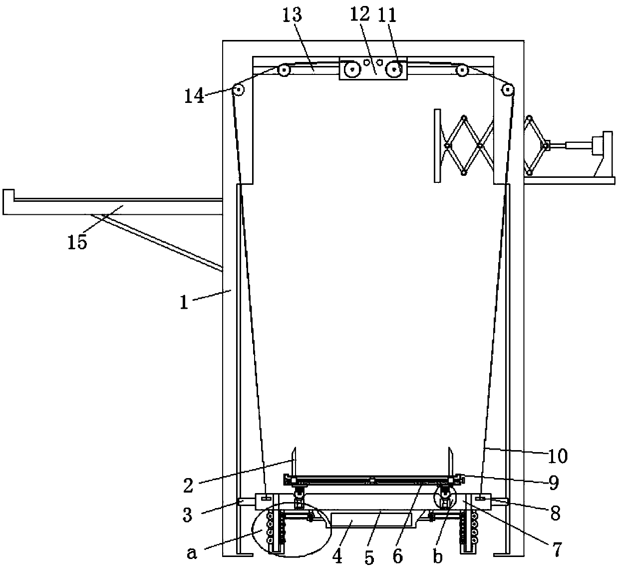
[0003] The purpose of the present invention is to solve the problems of complex structure, poor overall stability, low safety in the transportation process of electric equipment, and time-consuming and laborious installation of electric equipment in the prior art, and proposes a lifting device for installing electric equipment

Method used


Image

  • Electrical equipment installing and lifting device
  • Electrical equipment installing and lifting device
  • Electrical equipment installing and lifting device

Examples


Embodiment Construction

[0018] The following will clearly and completely describe the technical solutions in the embodiments of the present invention with reference to the accompanying drawings in the embodiments of the present invention. Obviously, the described embodiments are only some, not all, embodiments of the present invention.

[0019] In describing the present invention, it should be understood that the terms "upper", "lower", "front", "rear", "left", "right", "top", "bottom", "inner", " The orientation or positional relationship indicated by "outside", etc. is based on the orientation or positional relationship shown in the drawings, and is only for the convenience of describing the present invention and simplifying the description, rather than indicating or implying that the referred device or element must have a specific orientation, so as to Specific orientation configurations and operations, therefore, are not to be construed as limitations on the invention.

[0020] refer to Figure ...


PUM


Abstract

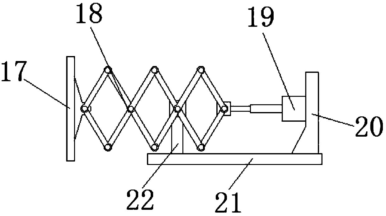
The invention discloses a lifting device for installing electric equipment, which comprises a column, and the column is symmetrically divided into left and right sides, and each side column is provided with a chute, and each of the chute is slidably connected with a slider. The end of each slider far away from the chute is jointly connected with a lifting plate, and the lifting plate is a cart, and a two-way threaded rod is horizontally arranged in the cart, and a moving block is symmetrically arranged on the two-way threaded rod, and each The moving blocks are provided with clamping blocks, and the upper ends of the clamping blocks run through the trolley, the lower end of the trolley is provided with a leg, the leg is provided with a connecting plate, and the lower end of the connecting plate is provided with an extension leg, and The lower end of the extension leg runs through the support leg, a spring is arranged on the connecting plate, a pulley is rotatably connected to the lower end of the extension leg, and a groove is arranged on the lifting plate. The invention has a stable structure, a simple overall structure, good safety in the transportation process of the electric equipment, and convenient installation of the electric equipment, which can save a lot of time and energy of the staff, and is worthy of popularization.

Description

technical field [0001] The invention relates to the technical field of electric equipment installation lifting equipment, in particular to an electric equipment installation lifting device. Background technique [0002] During the installation or transportation of electric equipment, for heavy electric equipment, in the prior art, a plurality of workers often cooperate to carry the electric equipment. It not only consumes manpower, but also has low efficiency and is prone to safety accidents. If the power equipment is too heavy, it is impossible to lift and transport the power equipment only by manpower. The existing power equipment installation and lifting equipment has a complex structure, poor overall stability, low safety in the transportation process of power equipment, and time-consuming and laborious installation of power equipment. Contents of the invention [0003] The purpose of the present invention is to solve the problems in the prior art of complex structur...

Claims


Application Information

Patent Timeline
Patent Type & Authority Applications(China)
IPC IPC(8): B66F11/00
CPCB66F11/00
Inventor 张然高雪花
Owner 成都课迪科技有限公司
Learn More