Wood drying box for furniture production

A drying box and wood technology, applied in the field of drying box, can solve the problems that the drying box cannot realize hot air circulation, increase production cost, heat loss, etc., achieve good practical effect, improve use efficiency, place and take convenient effect

Inactive Publication Date: 2018-02-02
湖州南浔雷欧木制品厂
View PDF0 Cites 4 Cited by
  • Summary
  • Abstract
  • Description
  • Claims
  • Application Information

AI Technical Summary

Benefits of technology

This technology allows for better utilization of warmth from an oven by allowing it to flow back upwardly along its own internal passageways within multiple layers of material before being dried on another layer. It also includes a system where fans can be used instead of just suckers or motors at both ends of the device's circulating pipes. By connecting this system to the outside of the machine, there may still be problems when trying to connect them properly due to differences between their designs.

Problems solved by technology

The technical problem addressed by this patented technology relates to controlling the moisten level during manufacturing processes when making furniture with various types or compositions of lumber being processed through traditional methods such as sawmills or mills. Current dryers have limitations because they can only remove water from certain parts of the wooden piece but may lose too much moistery at other locations where excessive moisturization occurs. This results in increased production cost over time.

Method used


Image

  • Wood drying box for furniture production
  • Wood drying box for furniture production
  • Wood drying box for furniture production

Examples


Embodiment Construction

[0015] In order to make the technical means, creative features, goals and effects achieved by the present invention easy to understand, the present invention will be further described below in conjunction with specific embodiments.

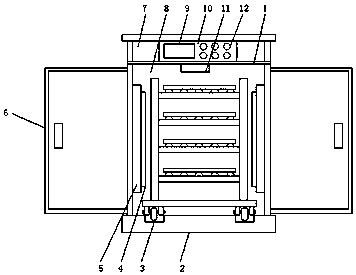
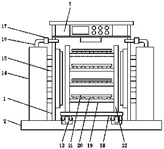
[0016] Such as Figure 1-3 As shown, a wood drying box for furniture production includes a drying box body 1 and a drying inner cavity 8, the top of the drying box body 1 is provided with a top box 7, and the surface of the top box 7 is provided with a control Panel 10, the surface of the control panel 10 is provided with a display screen 9 and function buttons 12, the bottom of the drying box 1 is fixedly installed with a base 2, and one side of the drying box 1 is hinged with a drying The box cover 6, the inside of the drying box 1 is provided with a drying inner cavity 8, the top of the drying inner cavity 8 is provided with a temperature sensor 11, and the side wall of the drying inner cavity 8 is installed There is a heating chamber 5, one s...


PUM


Abstract

The invention discloses a wood drying box for furniture production, which comprises a drying box body and a drying inner cavity. A top box is arranged on the top of the drying box body, and a control panel is arranged on the surface of the top box. The surface of the control panel is provided with a display screen and function buttons, the bottom of the drying box is fixedly installed with a base, one side of the drying box is hinged with a drying box cover, and the inside of the drying box is A drying inner cavity is provided, and a temperature sensor is arranged on the top of the drying inner cavity. A circulation pipe is connected to one side of the drying inner cavity, and one end of the circulation pipe is connected to the suction fan, and the suction fan is connected to the blower box through the circulation pipe, and the suction fan passes some heat in the drying inner cavity through the circulation pipe. Inhaled into the blower box, the blower box enters the heating chamber through the air guide pipe for heating again, and then the wood is dried through the air outlet, so that the hot air circulates in the drying inner cavity and improves the use efficiency of the hot air.

Description


Claims


Application Information

Patent Timeline
Owner 湖州南浔雷欧木制品厂
Why Eureka
Try Eureka