A pre-stack time migration imaging method of common scattering points based on time depth scanning

A technology of pre-stack time migration and imaging method, applied in seismology, instruments, measurement devices, etc., can solve the problems of impairing imaging effect, difficult application of migration imaging method, increasing calculation amount and workload, etc., to improve imaging. effect, achieve the effect of reliable offset imaging

Active Publication Date: 2019-05-31
INST OF GEOLOGY & GEOPHYSICS CHINESE ACAD OF SCI
View PDF4 Cites 0 Cited by
  • Summary
  • Abstract
  • Description
  • Claims
  • Application Information

AI Technical Summary

Problems solved by technology

[0008] In summary, most of the existing migration imaging methods are highly dependent on velocity, and a reliable velocity model is the key to obtaining good imaging results. Although the conventional scattered wave prestack migration imaging method based on the equivalent The dependence of the velocity model is greatly reduced, but a suitable initial velocity model is a necessary condition in the process of mapping CSP gathers. Unreliable velocity will damage the imaging effect, so it often requires multiple iterations of velocity analysis and CSP gather mapping , which increases the amount of calculation and work. However, for seismic data with low signal-to-noise ratio, it is often difficult to obtain relatively accurate velocities, and the existing migration imaging methods are also difficult to apply

Method used


Image

  • A pre-stack time migration imaging method of common scattering points based on time depth scanning
  • A pre-stack time migration imaging method of common scattering points based on time depth scanning
  • A pre-stack time migration imaging method of common scattering points based on time depth scanning

Examples


Embodiment Construction

[0052] The present invention will be described in more detail below in conjunction with the accompanying drawings and embodiments.

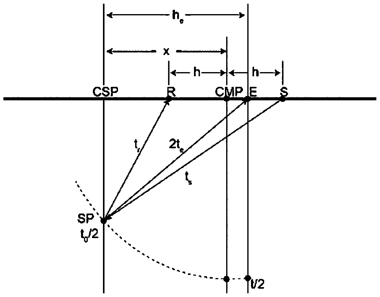
[0053] The invention discloses a time-depth scanning-based common-scattering point pre-stack time migration imaging method, which is based on the equivalent-offset common-scattering point pre-stack migration imaging method proposed by Bancroft et al. (1994, 1998) , to construct the equivalent offset h e :

[0054] Please refer to figure 1 , x is the distance from the common center point (CMP) to the scattered point on the ground projection point (CSP), h is the half-offset distance, t 0 is the self-excitation and self-collection travel time of the scattering point at the ground projection point (x=0, h=0). This figure shows the real propagation path of the seismic wave, that is, from the source point S to the scattering point SP to the receiving point R, and the self-excited and self-receiving path corresponding to the equivalent offset from p...


PUM


Abstract

The invention discloses a common scattering point pre-stack time migration imaging method based on time depth scanning. The method comprises the following steps: S1) reading in seismic input trace data; S2) determining a middle point coordinate of common scattering point gathers needing to be mapped, and starting from a middle point of the common scattering point gathers, selecting he increasinglyat the two sides with a step length delta h, and carrying out steps S3 and S4 in a loop manner till reaching maximum offset distance of the common scattering point gathers; S3) for any he, starting from the 0 moment, selecting time depth t0 increasingly with a step length delta t till maximum recording time t<max>R; S4) stacking values of sampling points of input traces at the t moment to recording points of recording traces, the equivalent offset distance of which is he, in the common scattering point gathers at the same moment; S5) repeating the steps S1)-S4) until all input traces are mapped to different common scattering point gathers respectively; and S6) finishing pre-stack time migration imaging through reflection wave seismic processing software. The method does not need an initial velocity model, can process low signal-to-noise-ratio data and realize reliable migration imaging.

Description

technical field [0001] The invention relates to a seismic data migration imaging method, in particular to a pre-stack time migration imaging method of common scattering points based on time-depth scanning. Background technique [0002] Migration imaging, also known as relocation processing, migration homing processing, imaging processing or delay processing, is the last and most important part of conventional seismic data processing. Seismic migration imaging profile is the imaging result of underground stratum and structure, and is one of the most important achievements of seismic exploration. The reliability and accuracy of migration imaging are directly related to the effectiveness of related exploration such as oil and gas resources, mineral resources and engineering. [0003] According to the nature of the input seismic data and the sequence of migration and stacking, migration imaging techniques can be divided into post-stack migration and pre-stack migration. The pos...

Claims


Application Information

Patent Timeline
Patent Type & Authority Patents(China)
IPC IPC(8): G01V1/28
CPCG01V1/28G01V2210/512
Inventor 张美根
Owner INST OF GEOLOGY & GEOPHYSICS CHINESE ACAD OF SCI
Why Eureka
Try Eureka