Motor winding and winding method

A winding method and technology for motor windings, which are used in electric components, manufacturing of motor generators, shape/style/structure of winding conductors, etc., can solve the problem of unfavorable uniform magnetic field distribution and magnetic field conduction of multi-lobe stators, and product quality is difficult to control. The problem of high production cost, to reduce the quality weak point, eliminate the coil solder joint, and achieve the effect of low cost

Pending Publication Date: 2018-02-02
SUZHOU AMTF ROBOTS CO LTD
View PDF6 Cites 2 Cited by
  • Summary
  • Abstract
  • Description
  • Claims
  • Application Information

AI Technical Summary

Problems solved by technology

The process of this method is extremely complicated, and due to the existence of a large number of solder joints, the product quality is difficult to control, and the production cost is high and difficult.
Other existing technologies are mainly to pre-press the conductors and design the stator into a multi-lobe structure to form a stator. The structure is complex, and the multi-lobe stator is not conducive to the uniform distribution of the magnetic field and the conduction of the magnetic field.

Method used


Image

  • Motor winding and winding method
  • Motor winding and winding method
  • Motor winding and winding method

Examples


Embodiment Construction

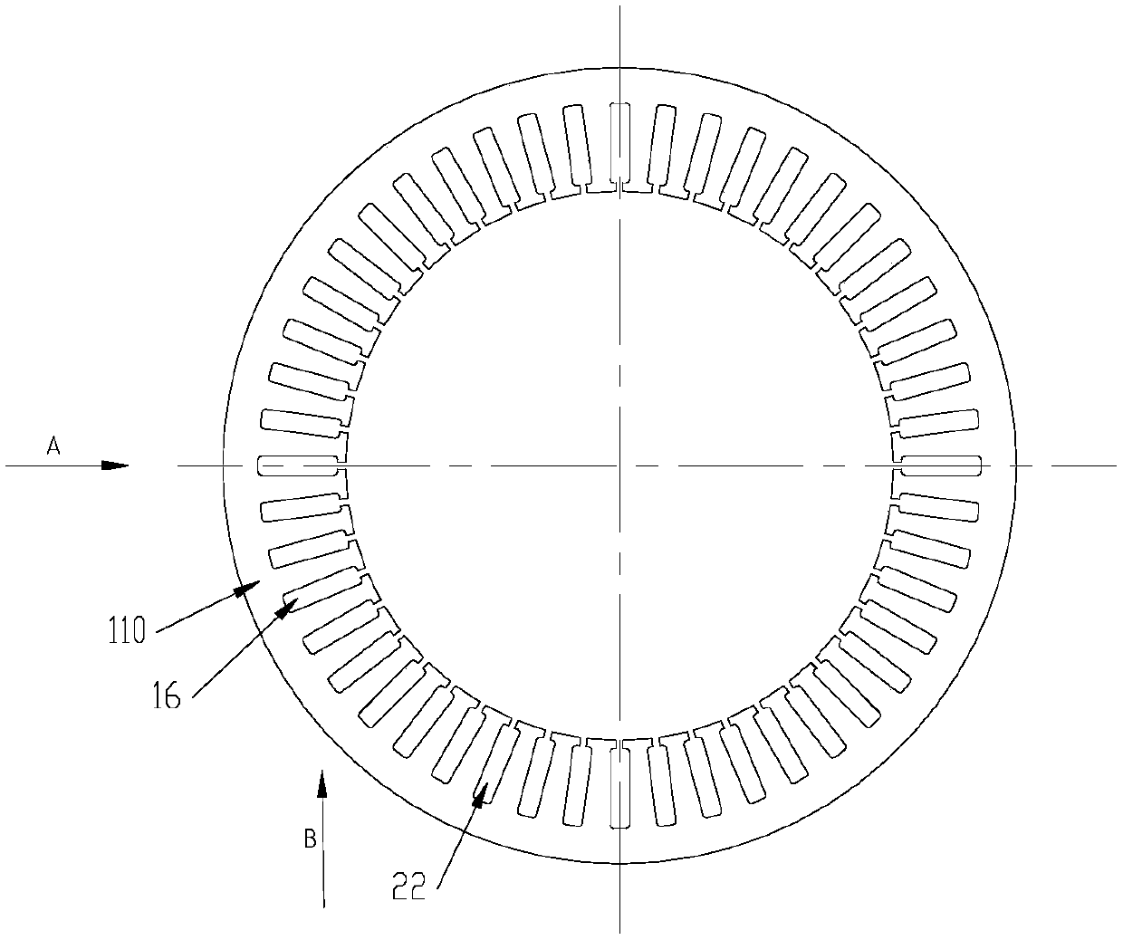
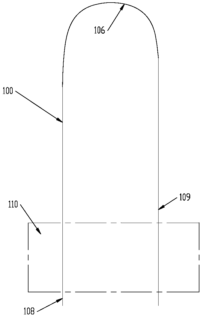
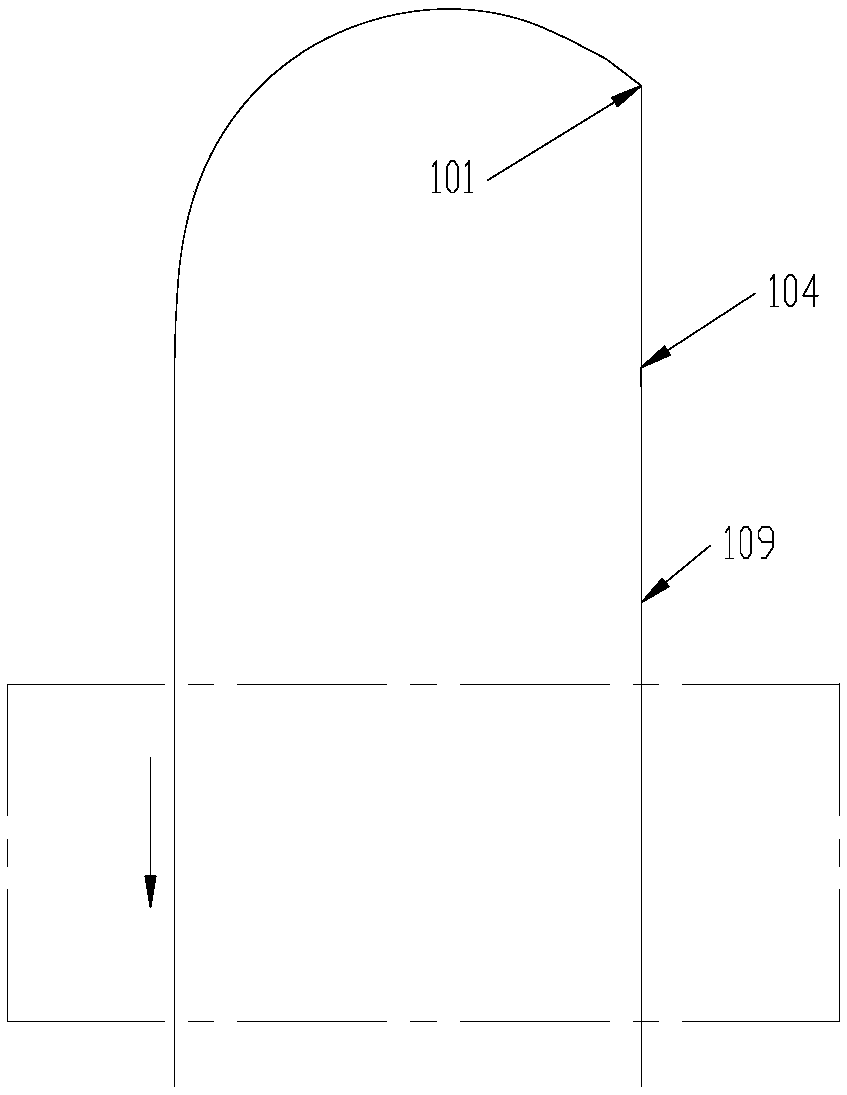
[0023] See Figure 2-7 The winding process of the one-turn coil shown in the winding method uses a long conductor 100 to pass through the slot 22 on the stator 110, and then the end of the conductor is turned back to form a U-shape 106, and the free end 108 of the conductor is removed from Insert the end of slot 16 into another slot 16 (see figure 2 ), the conductor is pulled through the wire slot 16, when the U-shaped part of the conductor is close to the iron core wire slot, while the conductor is being pulled, it is carried out at the first bending point 101 on the conductor leading end 109 drawn from the wire slot 22 First bend (see image 3 ), and then pull the conductor into the slot 16 gradually, and make a second bend at the second bending point 102 on the lead-out end of the conductor (see Figure 4 ), then insert the conductor into the wire slot 16, and perform a third bend at the third bending point 103 on the lead-out end of the conductor (see Figure 5 ), the second...


PUM


Abstract

The invention provides a winding method of a motor winding and the motor winding. By using the winding method and the motor winding, a technology is simple, production efficiency is high, cost is lowand the method and the winding can adapt to automation production. According to the motor winding made through using the method, a number of welding spots is less, weight weak points are reduced and reliability is high; and because a lot of welding is not needed, production efficiency is high and cost is low. In the winding method, one conductor is adopted and the following processes are repeatedtill that one conductor completes all or partial winding of one phase of winding. When one conductor completes the partial winding of the winding, leading-out terminals of partial windings are mutually connected so as to form one phase of winding. The repeated processes comprises that a free end of the conductor is inserted into a wire groove from a head end of one wire groove and is pulled out ofa tail end of the wire groove, and then the conductor carries out back bending; and the free end of the conductor is inserted into a tail end of the other wire groove and is pulled out of a head endof the other wire groove, and then the conductor carries out back bending. The motor winding comprises three phases of windings, and each phase of winding passes through one conductor of the wire groove or several connected conductors.

Description

Technical field [0001] The present invention relates to motor windings, in particular to a stator winding and its winding method. Background technique [0002] In today’s motor technology field, there is a large gap between the outer circles when the circular conductors that make up the windings are arranged with each other. Compared with the circular conductor, the flat conductor occupies a smaller space in the stator. Therefore, the flat conductor The windings composed of conductors (hereinafter referred to as flat wire windings) are gradually replacing the windings composed of round conductors (hereinafter referred to as round wire windings) and become the development direction of the current motor field. [0003] However, since the bending strength of the flat wire is much higher than the bending strength of the conductor bundle composed of multiple round conductors, it cannot be easily wound into the required shape like a round wire winding, and it cannot be like a round wire ...

Claims


Application Information

Patent Timeline
Patent Type & Authority Applications(China)
IPC IPC(8): H02K15/085H02K3/28H02K3/04
CPCH02K3/04H02K3/28H02K15/085H02K2213/03
Inventor 林中尉
Owner SUZHOU AMTF ROBOTS CO LTD
Why Eureka
Try Eureka