Light source plate, backlight module and display device

A light source board and substrate technology, which is applied in optics, nonlinear optics, static indicators, etc., can solve the problems that the active driving method cannot be achieved, and the driving current requirement of the LED cannot be applied, etc., to simplify the operability of the welding connection, and the welding is simple Convenient and easy to create effects

Active Publication Date: 2020-06-16
TCL CORPORATION
View PDF12 Cites 1 Cited by
  • Summary
  • Abstract
  • Description
  • Claims
  • Application Information

AI Technical Summary

Problems solved by technology

[0003] The purpose of the present invention is to provide a light source board, aiming to solve the technical problem that the existing active driving method cannot meet the current requirement for driving LED and cannot be applied to backlight driving

Method used


Image

  • Light source plate, backlight module and display device
  • Light source plate, backlight module and display device
  • Light source plate, backlight module and display device

Examples


Embodiment Construction

[0040] In order to make the object, technical solution and advantages of the present invention clearer, the present invention will be further described in detail below in conjunction with the accompanying drawings and embodiments. It should be understood that the specific embodiments described here are only used to explain the present invention, not to limit the present invention.

[0041] It should be noted that when a component is referred to as being “fixed on” or “disposed on” another component, it may be directly or indirectly on the other component. When an element is referred to as being "connected to" another element, it can be directly or indirectly connected to the other element. The orientation or positional relationship indicated by the terms "upper", "lower", "left", "right", etc. are based on the orientation or positional relationship shown in the drawings, and are for convenience of description only, rather than indicating or implying the referred device Or ele...


PUM


Abstract

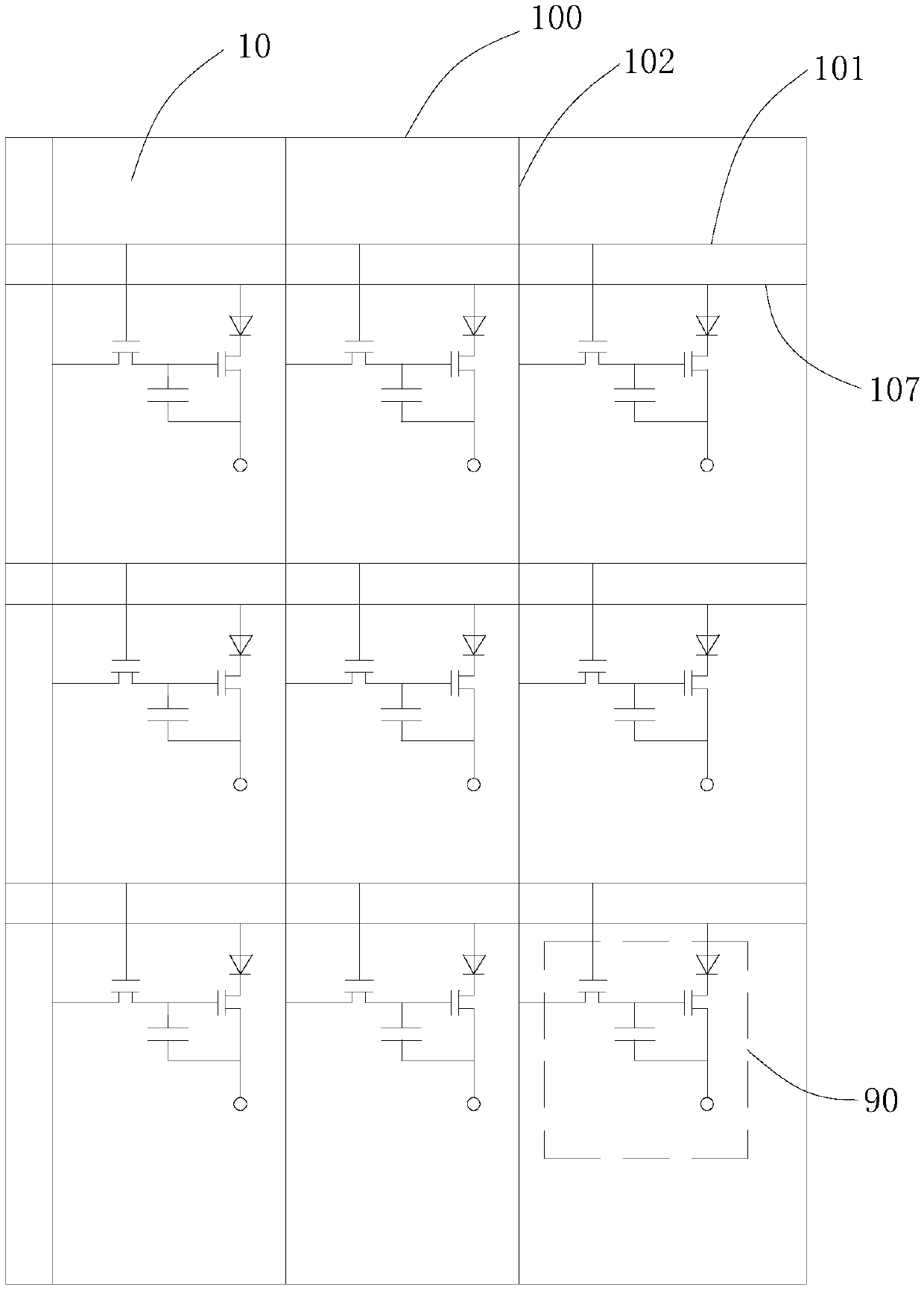
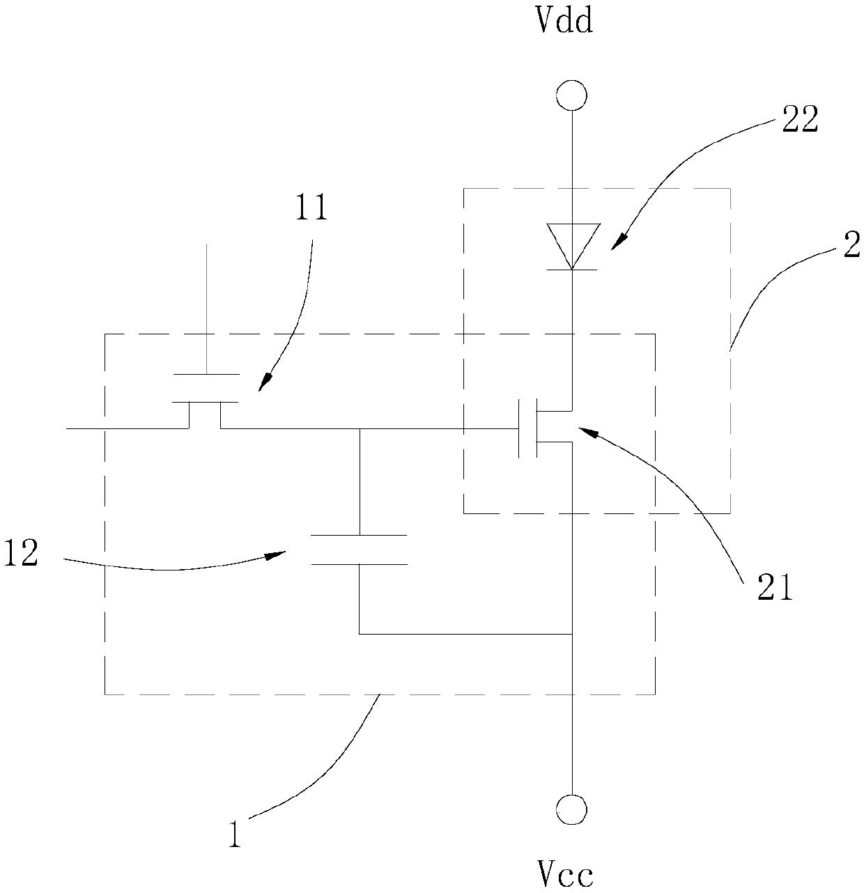
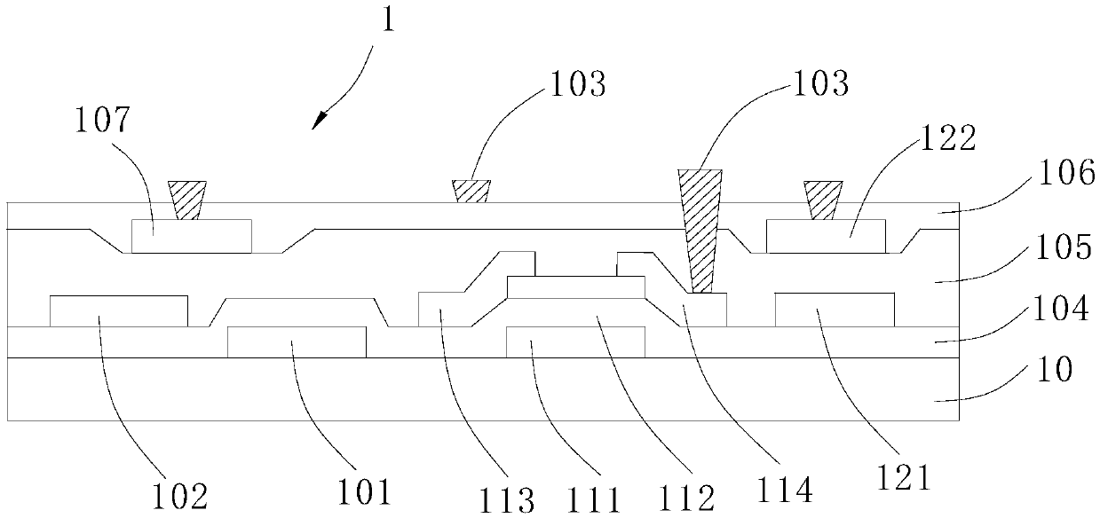
The invention applicable to the technical field of display provides a light source plate, a backlight module and a display device. The light source plate comprises a driving substrate and a light-emitting packaging assembly. The driving substrate comprises a first substrate body, a switch element and a capacitor element, wherein the switch element and the capacitor element are arranged on the first substrate body. The light-emitting packaging assembly arranged on the driving substrate comprises a second substrate, a driving element and a light-emitting element, wherein the driving element andthe light-emitting element are packaged on the second substrate in a discrete element mode. According to the invention, the driving element and the light-emitting element are packaged on the second substrate in the form of discrete elements to form the light-emitting packaging assembly; the driving element can directly adopt an MOS tube discrete element capable of bearing a large driving current at present; the requirement for driving current of a light-emitting element used as backlight is met, the backlight technology that driving is conducted in an active driving mode is achieved, the driving substrate is easier to manufacture and larger in size, welding between the driving substrate and the light-emitting packaging assembly is simpler and more convenient, and operability of welding andassembling of the light source plate is simplified.

Description

technical field [0001] The invention belongs to the field of display technology, and in particular relates to a light source plate, a backlight module and a display device. Background technique [0002] At present, most LED (Light-Emitting Diode, light-emitting diode) backlight technologies are produced by soldering LEDs on a PCB (Printed Circuit Board, printed circuit board) backplane, and are driven statically or passively. The TFT (Thin Film Transistor, Thin Film Transistor) driving backplane is used to drive a liquid crystal panel or an OLED display panel, which can drive pixel units or light-emitting elements in an active manner, and has the advantages of high contrast and energy saving. However, the driving current required by the pixel units or light-emitting elements of the liquid crystal panel or the OLED display panel is small, and the current density that the TFT backplane can withstand is small, which cannot reach the current density required for driving the LED....

Claims


Application Information

Patent Timeline
Patent Type & Authority Applications(China)
IPC IPC(8): G02F1/13357G09G3/34
CPCG02F1/133603G09G3/3406G02F1/133612
Inventor 谢相伟马刚林智远陈光郎闫晓林
Owner TCL CORPORATION
Why Eureka
Try Eureka