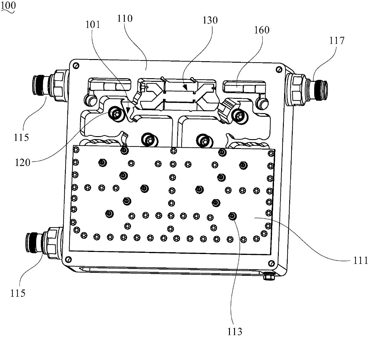
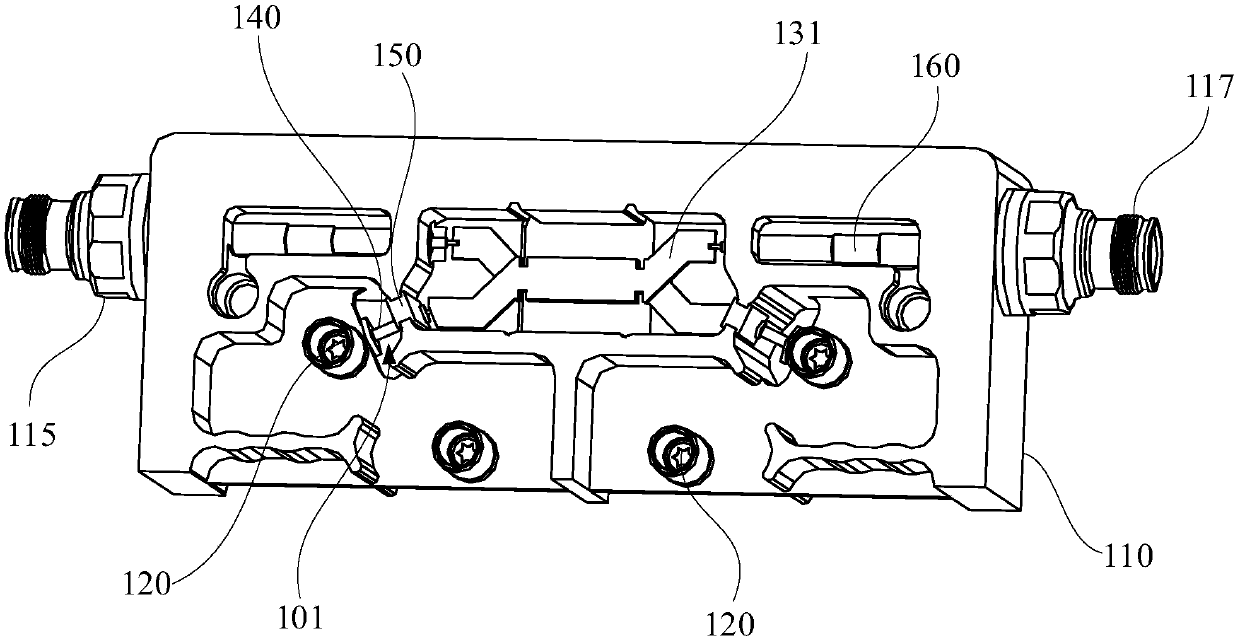
Bridge combiner

A combiner and bridge technology, which is applied in the field of microwave radio frequency devices, can solve problems such as the complex structure of the bridge combiner, and achieve the effects of compact structure, reduced welding operations, and reduced number of solder joints

Active Publication Date: 2019-04-02
COMBA TELECOM TECH (GUANGZHOU) CO LTD +1
View PDF4 Cites 1 Cited by
  • Summary
  • Abstract
  • Description
  • Claims
  • Application Information

AI Technical Summary

Problems solved by technology

[0005] Based on this, it is necessary to provide a bridge combiner with a simplified structure in view of the complex structure of the existing bridge combiner

Method used


Image

  • Bridge combiner
  • Bridge combiner
  • Bridge combiner

Examples


Embodiment Construction

[0025] In order to facilitate the understanding of the present invention, the present invention will be described more fully below with reference to the associated drawings. Preferred embodiments of the invention are shown in the accompanying drawings. However, the present invention can be embodied in many different forms and is not limited to the embodiments described herein. On the contrary, these embodiments are provided to make the understanding of the disclosure of the present invention more thorough and comprehensive.

[0026] It should be noted that when an element is referred to as being “fixed” to another element, it can be directly on the other element or there can also be an intervening element. When an element is referred to as being "connected to" another element, it can be directly connected to the other element or intervening elements may also be present. The terms "vertical," "horizontal," "left," "right," and similar expressions are used herein for purposes ...


PUM


Abstract

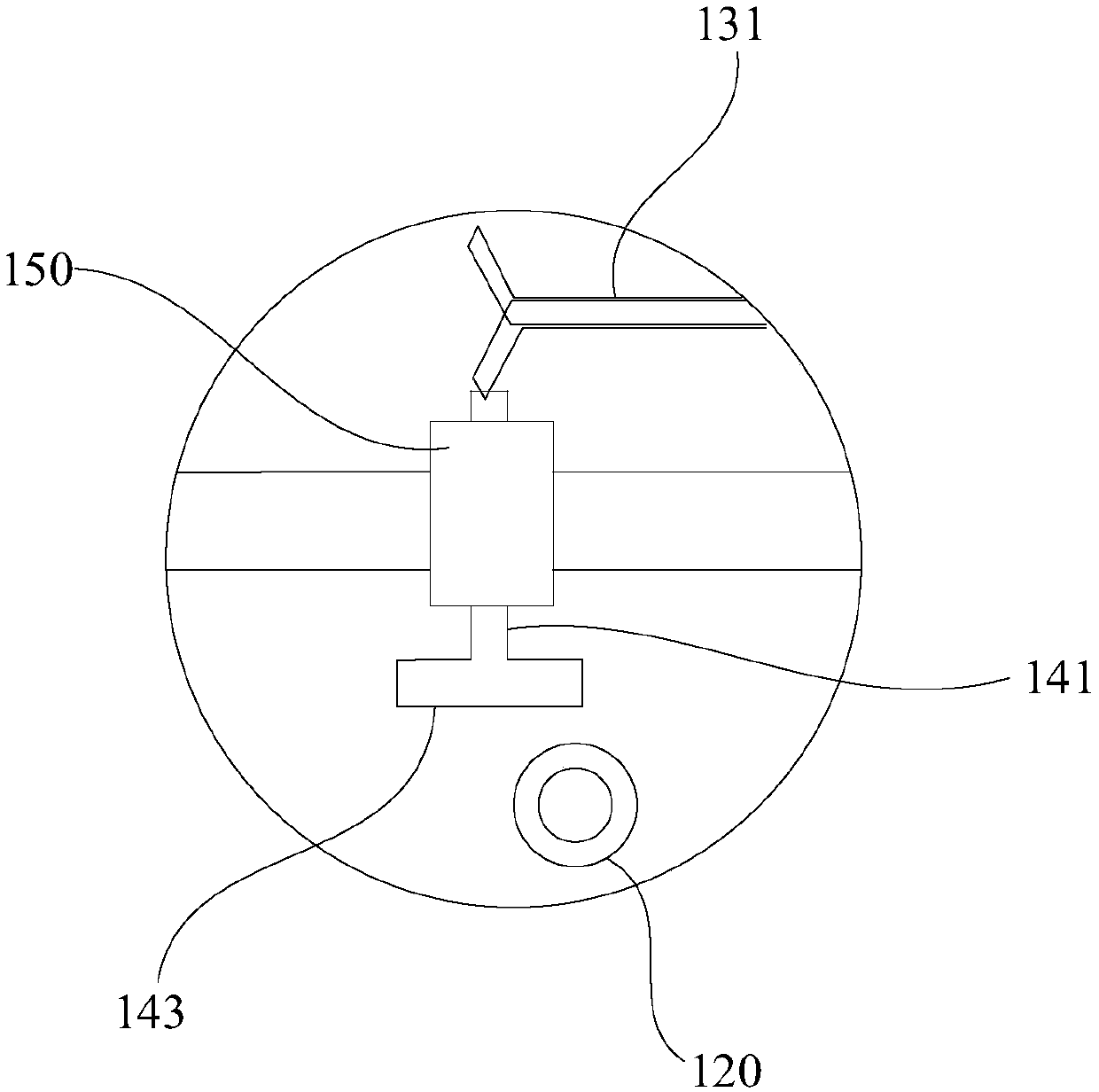
The invention relates to a bridge combiner. The bridge combiner comprises a cavity, a bridge structure, filter structures composed of a plurality of resonators, and coupling structures. The bridge structure and the filter structures are integrated in the cavity, so that the structure is compact and the volume is reduced. The resonator of the first-cavity filter structure is electrically coupled with a bridge port of a bridge conduction band sheet through the corresponding coupling structures, coupling discs are not in direct contact with the resonators, and the conduction of signals between the bridge structure and the filter structures is realized in an electric coupling manner. Compared with a traditional structure, according to the bridge combiner, the bridge structure is connected withthe filter structures without using cables or connectors, and the welding operation can be reduced obviously, so that the quantity of welding spots is reduced. Moreover, one coupling structure can realize electric coupling with the filter structures simultaneously. Therefore, the structure of the bridge combiner can be simplified effectively.

Description

technical field [0001] The invention relates to the technical field of microwave radio frequency devices, in particular to a bridge combiner. Background technique [0002] The bridge combiner structure is an electrical structure that integrates the functions of the bridge and the combiner. It is mainly used in POI (multi-system combining platform), and the isolation between systems is improved through the bridge. In the bridge combiner structure, it is necessary to connect the bridge to the filter. At present, the main connection methods include cable jumper connection and integrated connection. [0003] The cable jumper connection method is to use cables and connectors to connect the bridge and filter. This method requires additional cables and connectors to be introduced into the structure of the bridge combiner, and requires complicated assembly and debugging. The integrated welding method is to connect the bridge guide strip and the first cavity resonant column of the ...

Claims


Application Information

Patent Timeline
Patent Type & Authority Applications(China)
IPC IPC(8): H01P1/213H01P5/16
CPCH01P1/2138H01P5/16
Inventor 金志刚丁海陈凯靳雲玺
Owner COMBA TELECOM TECH (GUANGZHOU) CO LTD
Why Eureka
Try Eureka