Packing box pod for unmanned aerial vehicle logistics

A technology of drones and cargo boxes, which is applied to cargo box pods and mounted on the field of cargo box pods of drones. It can solve the problems of personnel injury, damage to drones, and loss of goods, and achieve improved automation. The degree of improvement, the effect of improving operating efficiency and reducing misoperation accidents

Pending Publication Date: 2018-02-09
厦门大壮深飞科技有限公司
View PDF0 Cites 1 Cited by
  • Summary
  • Abstract
  • Description
  • Claims
  • Application Information

AI Technical Summary

Problems solved by technology

Most of the existing container pods are loaded and unloaded manually, which is not conducive to intelligent centralized operation, and is prone to human misoperation, resulting in accidents such as damage to drones, personnel injuries, or loss of goods

Method used


Image

  • Packing box pod for unmanned aerial vehicle logistics
  • Packing box pod for unmanned aerial vehicle logistics
  • Packing box pod for unmanned aerial vehicle logistics

Examples


Embodiment 1

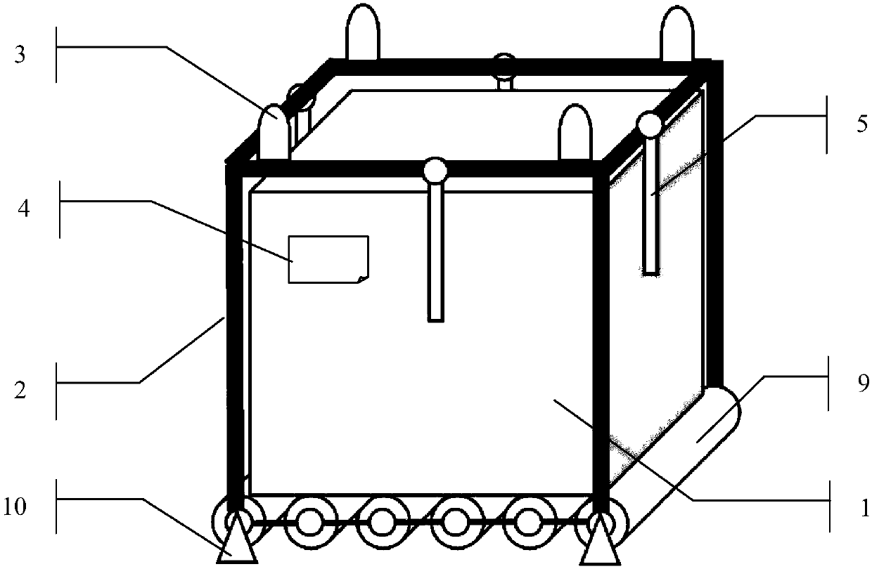
[0032] The container pod includes a container liner 1, a container shell 2, a container fixing mechanism 3, a logistics label 4, a locking mechanism 5, a communication module 6, a power supply unit 7, and a central controller 8, wherein,

[0033] The container liner 1 is used to carry the package to be transported. The container liner 1 is a square box (open at the top, with or without a cover. If there is no cover, the container shell 2 needs a top cover) ;

[0034] Such as figure 1 with figure 2 As shown, the container shell 2 adopts a frame structure, or it can be a frame with only a top cover, so that the container liner 1 can be pushed out after landing, and each frame is fixedly connected; the bottom surface of the container shell 2 has Rolling mechanism 9, the rolling mechanism 9 is composed of a plurality of axially parallel cylinders, used for loading and unloading the container liner 1, the axial direction of the rolling mechanism 9 is perpendicular to the directi...

Embodiment 2

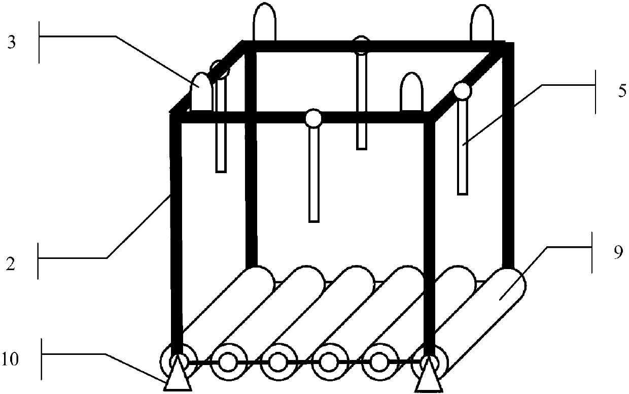
[0052] like Image 6 , The container shell 2 is a square box frame structure with openings at both ends, that is, there are guard plates on both sides of the opening. The container shell 2 is provided with a window 13, and the area of ​​the window 13 is greater than or equal to the area of ​​the logistics label of the container liner 1, and the height of the window 13 should ensure that when the container liner 1 is installed in place, the logistics label of the container liner 1 is just from the The window 13 is exposed.

[0053] Further, a liquid crystal screen is provided on the outer surface of the container liner 1, and the electronic label is displayed on the liquid crystal screen of the container liner.

Embodiment 3

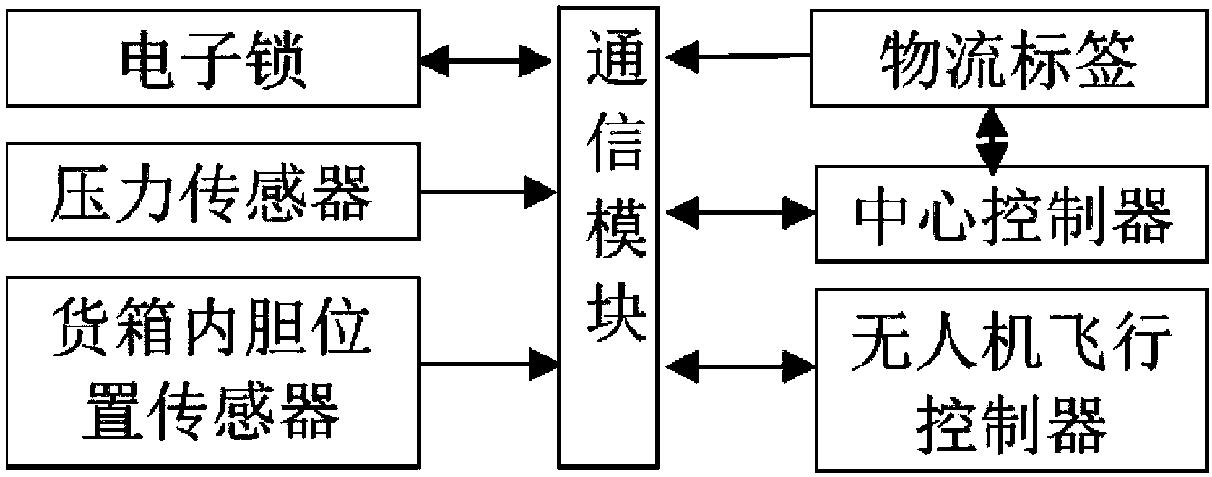
[0055] As preferably, the cargo box shell 2 of the cargo box pod also includes a cargo box liner position sensor, which is connected with the electronic lock through the communication module 6. When loading, when the cargo box liner position sensor knows that the cargo box liner 1 When it is inside the container shell 2 and has reached the predetermined position, the central controller 8 controls the electronic lock to perform a locking operation to lock the container liner 1 in the container shell 2 . See image 3 .


PUM


Abstract

The invention discloses a packing box pod for unmanned aerial vehicle logistics, and belongs to the technical field of unmanned aerial vehicles. The scheme of combining an inner container with an outer shell is adopted. A rolling mechanism is arranged at the bottom of the packing box outer shell, and the packing box inner container can be limited into the packing box outer shell through an electronic lock and a limiting stopper. By adoption of the structure, an approach of connecting the unmanned aerial vehicle logistics with ground operations is provided, logistics transportation (especiallycontainer transportation) of an unmanned aerial vehicle can be facilitated, the degree of automation is increased and misoperation accidents caused by manual unloading are reduced; and moreover, various flexible and convenient implementation modes are available, and logistics operating efficiency of the unmanned aerial vehicle is effectively improved.

Description

technical field [0001] The invention relates to a container pod, in particular to a container pod mounted on an unmanned aerial vehicle. It belongs to the field of unmanned aerial vehicle technology. Background technique [0002] With the development of UAV technology, its fields of use are increasing. UAVs perform a large number of operations in plant protection, logistics, power line inspection, etc. The next stage of UAV development is UAV robots. A high degree of automation and intelligence can replace manual labor to complete more sophisticated and complex tasks. Among them, the transportation of materials, that is, logistics, is an important application field of drones. Some rural areas in my country have launched drone logistics pilots, but their degree of autonomy is very high. It depends on the structure of the container pod, especially the convenient loading and unloading of the container pod with generalization and modularization is still a technical problem to be ...

Claims


Application Information

Patent Timeline
IPC IPC(8): B65D88/12B65D90/20
CPCB65D88/12B65D90/20
Inventor 不公告发明人
Owner 厦门大壮深飞科技有限公司
Why Eureka
Try Eureka