Impeller aligning method of wind turbine generator system

A technology for wind turbines and impellers, which is applied in the assembly of wind turbines and wind power generation. It can solve the problems of broken blades, long hoisting hours, and high safety factor, and achieve the effects of convenient installation and reduced site requirements.

Inactive Publication Date: 2018-02-09
NANJING ZHONGREN ENERGY TECH
View PDF9 Cites 5 Cited by
  • Summary
  • Abstract
  • Description
  • Claims
  • Application Information

AI Technical Summary

Problems solved by technology

[0002] At present, hub pitch in the wind power industry is divided into electric pitch and hydraulic pitch. Both pitch methods have their advantages and disadvantages. For electric pitch, it is convenient to install blades on site, but its stability is poor and the failure rate is high. Therefore, in order to improve the stability of the unit, many OEMs use hydraulic pitch, but the hydraulic pitch can only be adjusted within a range of 90 degrees, which puts forward higher requirements for on-site hoisting and restricts the installation of impellers on site.
Under the condition of hydraulic pitch change, the installation method of the hub can be front-mounted or reverse-mounted. When the impeller is lifted by the reverse-mounted hub, the tail of the auxiliary hanger is the front edge of the blade. When the impeller is lifted by the hub, the tail of the auxiliary hanger is the front edge of the blade Compared with the trailing edge, the leading edge of the reverse-mounted sliding tail blade has a higher safety factor, and there are no problems such as blade breakage and deformation. However, this installation method takes a long time for hoisting, which brings about an increase in hoisting costs. To reduce the hoisting man-hours and hoisting costs, it is necessary to adopt the hoisting method of the trailing edge of the sliding tail blade, but this hoisting method has the risk of blade breakage and deformation

Method used


Image

  • Impeller aligning method of wind turbine generator system
  • Impeller aligning method of wind turbine generator system

Examples


Embodiment Construction

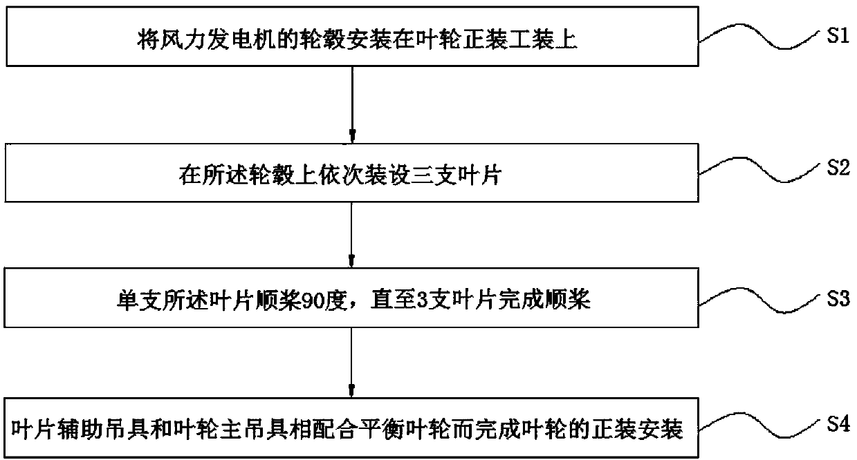
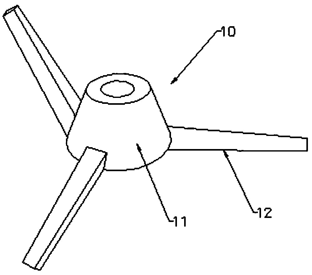
[0017] Such as figure 1 As shown, a schematic flow chart of a wind turbine impeller installation method, in this embodiment, the impeller installation equipment is used, and the impeller installation equipment includes the auxiliary blade spreader, the blade trailing edge protector, the impeller main spreader and the impeller installation tooling, And the wind turbine impeller installation method includes the following steps: S1: install the hub of the wind generator on the impeller installation tooling; S2: install three blades on the hub in sequence, first, by adjusting the position of the center of gravity of the blade auxiliary hanger to the The line connecting the center of gravity of the blade is perpendicular to the blade, and the blade trailing edge protector is installed on the blade trailing edge of the blade; secondly, the blade auxiliary sling is fixed on the blade trailing edge of the blade to lift the blade; again, Rotate the blades, and finally, install the blad...


PUM


Abstract

The invention provides an impeller aligning method of a wind turbine generator system, and belongs to the technical field of wind turbine generator systems. The impeller aligning method of the wind turbine generator system comprises the following steps: (S1) a hub of a wind driven generator is mounted on an impeller aligning tool; (S2) three blades are mounted on the hub in sequence; connecting lines between the gravity center positions of blade auxiliary lifters and the gravity center positions of the blades are perpendicular to the blades; blade back edge protectors are mounted in the bladeback edge positions of the blades; the blade auxiliary lifters lift the blades through fixing in the blade back edge positions of the blades; and the blades are rotated and mounted on the hub; (S3) single blade is feathered by 90 degrees until three blades are feathered; and (S4) the blade back edge position of one blade is fixed through the blade auxiliary lifters; the hub is fixed through an impeller main lifter; and the blade auxiliary lifters and the impeller main lifter are matched to balance the impeller to finish the aligning installation of the impeller. The lifting time and the lifting cost can be reduced; and meanwhile, the blade rupture and deformation risks can be reduced.

Description

technical field [0001] The invention belongs to the technical field of wind power generators, and in particular relates to a front-mounting method for impellers of wind power generators. Background technique [0002] At present, hub pitch in the wind power industry is divided into electric pitch and hydraulic pitch. Both pitch methods have their advantages and disadvantages. For electric pitch, it is convenient to install blades on site, but its stability is poor and the failure rate is high. Therefore, in order to improve the stability of the unit, many OEMs use hydraulic pitch, but the hydraulic pitch can only be adjusted within a range of 90 degrees, which puts forward higher requirements for on-site hoisting and restricts the installation of impellers on site. Under the condition of hydraulic pitch change, the installation method of the hub can be front-mounted or reverse-mounted. When the impeller is lifted by the reverse-mounted hub, the leading edge of the blade is th...

Claims


Application Information

Patent Timeline
Patent Type & Authority Applications(China)
IPC IPC(8): F03D13/10
CPCY02E10/72F03D13/10
Inventor 黎旋
Owner NANJING ZHONGREN ENERGY TECH
Why Eureka
Try Eureka