
Radar fill level measurement device

A material level measurement and radar technology, applied in the field of radar material level measurement devices, can solve the problems of average transmit power or reduction of average transmit power, etc., and achieve the effect of reliable adjustment

Active Publication Date: 2018-02-09
VEGA GRIESHABER GMBH & CO
View PDF9 Cites 2 Cited by
  • Summary
  • Abstract
  • Description
  • Claims
  • Application Information

AI Technical Summary

Problems solved by technology

If the measuring signal is not transmitted without interruption, especially the high-frequency content of the transmitted measuring signal, the mean transmit power or the mean transmit power of the radar level measuring device may be correspondingly reduced in this way

Method used


Image

  • Radar fill level measurement device
  • Radar fill level measurement device
  • Radar fill level measurement device

Examples


Embodiment Construction

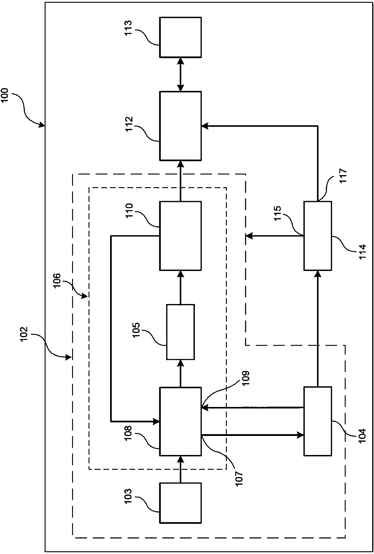
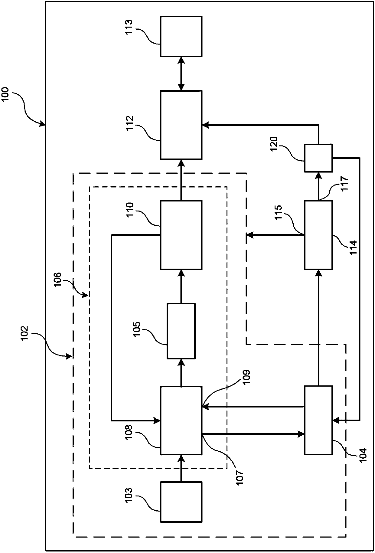
[0038] figure 1 is a schematic diagram of a radar level measuring device 100 according to an embodiment of the present invention, and each component of the radar level measuring device 100 is shown as a block diagram.

[0039] The radar level measuring device 100 comprises a frequency synthesizer 102 for generating an oscillating signal. The frequency synthesizer 102 includes a control unit 104 , a reference oscillator 103 and a phase locked loop 106 .

[0040] The phase-locked loop 106 includes a phase-locked element 108 or a PLL component 108 , and a reference signal generated by the reference oscillator 103 is supplied to the phase-locked element 108 or the PLL component 108 via a corresponding input terminal. Furthermore, the phase-locked loop 106 includes a loop filter 105 which is arranged between the phase-locked element 108 and the oscillator 110 . The phase-locked loop 106 is a closed control loop through which the phase position and / or frequency of the oscillator 1...


PUM


Abstract

A radar fill level measurement device (100) can be provided, which comprises a frequency synthesizer (102) configured to generate an oscillator signal, a high-frequency signal generation module (112)configured to generate a transmission signal based on the oscillator signal, and an energy-supply module (114) configured to supply electrical energy to the frequency synthesizer (102) and the high-frequency signal generation module (112). The frequency synthesizer (102) can comprise a control device (104), a reference oscillator (103) and a phase-locked loop (106). The phase-locked loop (106) cancomprise a phase-locked device (108) and an oscillator (110). The phase-locked loop (106) can be configured to adjust a frequency of the oscillator signal to a target value, and the phase-locked device (108) can be configured to provide a control signal for the control device (104) when the frequency of the oscillator signal has reached the target value. The control device (104) can also be configured to actuate the energy-supply module (114) to supply the electrical energy to the high-frequency signal generation module (112) before the control signal is provided by the phase-locked device (108).

Description

technical field [0001] The present invention relates generally to the field of radar-based level measurement. In particular the invention relates to a radar level measuring device, a method of operating a radar level measuring device, a program element for a radar level measuring device and a computer readable medium containing the program element. Background technique [0002] Radar level measuring devices, ie radar sensors for level measurement, comprise high frequency modules and / or high frequency circuits which are often operated in a timed manner. Such clocking involves alternately passing active periods of operation during which measurement signals are transmitted towards the filling material and inactive periods during which no measurement signals are transmitted. [0003] In order to save energy, all high-frequency modules or at least some components of the high-frequency module are disconnected from the energy supply, eg voltage supply and / or current supply, during...

Claims


Application Information

Patent Timeline
Patent Type & Authority Applications(China)
IPC IPC(8): G01F23/284
CPCG01F23/284G01S13/34G01S7/4017G01S7/034G01S13/40G01F23/244G01F25/10
Inventor 克里斯托弗·米勒丹尼尔·舒尔特海斯迈克尔·菲舍尔
Owner VEGA GRIESHABER GMBH & CO
Learn More