Isolation cell for sheath flow impedance counting device

A technology of counting device and sheath flow, applied in the direction of measuring device, instrument, biological particle analysis, etc., can solve the problem of affecting the accuracy of counting, and achieve the effect of good drainage, reduce impact force, and improve accuracy.

Inactive Publication Date: 2018-02-09
LEADWAY HK
View PDF13 Cites 1 Cited by
  • Summary
  • Abstract
  • Description
  • Claims
  • Application Information

AI Technical Summary

Problems solved by technology

When these splashed liquids fall into the bottom of the container, they will impact the liquid level at the bottom of the container, which will easily generate air bubbles that affect the counting accuracy

Method used


Image

  • Isolation cell for sheath flow impedance counting device
  • Isolation cell for sheath flow impedance counting device
  • Isolation cell for sheath flow impedance counting device

Examples


Embodiment 1

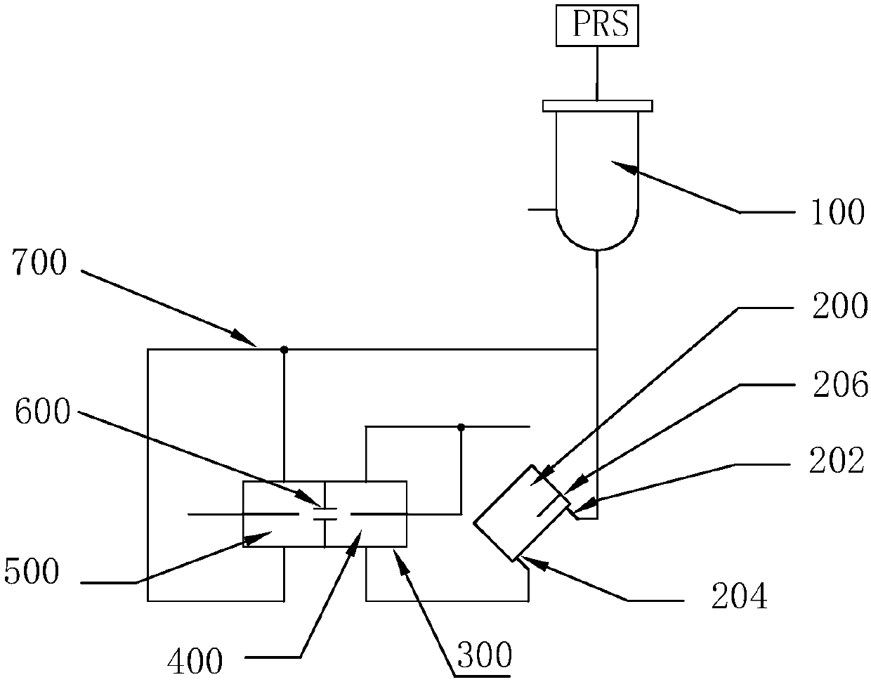
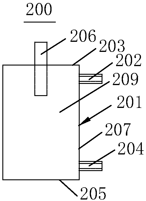
[0047] Please refer to figure 1 , the sheath flow impedance counting device of the present invention includes: a liquid storage tank 100 , an isolation tank 200 and a counting tank 300 . Wherein, the counting tank 300 includes a rear tank 400 , a front tank 500 and a counting hole 600 between the rear tank 400 and the front tank 500 . The isolation tank 200 includes a container body 201 , a liquid inlet 202 and a liquid outlet 204 , wherein the container body 201 includes a top wall 203 , a bottom wall 205 , and a side wall 207 . The top wall, bottom wall and side walls enclose the inner cavity 209 of the isolation tank. The container body 201 may be a cylinder, a cube, a regular polygon, a sphere, an ellipsoid, or a combination of a cylinder, a hemisphere or a cone, and the like. The liquid inlet 202 of the isolation tank is connected to the liquid storage tank 100 through a pipeline 700 (collectively referred to as all pipelines, the same throughout), and the liquid outle...

Embodiment 2

[0059] figure 2 and Figures 2A-2F Shown is a second embodiment of the invention. The main difference between the second embodiment and the first embodiment is that the angle between the stopper 206 and the top wall 203 of the isolation tank is 45 degrees, that is, the stopper 206 is isolated from the top wall 203 of the isolation tank. The inner cavity 209 of the pool extends and forms an angle of 45 degrees or 135 degrees with all planes of the top wall 203 of the isolation pool. The inventors have shown through experiments that the included angle between the stopper 206 and all the planes of the top wall 203 of the isolation tank can also be selected from: the angle greater than or equal to 30 degrees is less than or equal to the angle of 60 degrees, the angle greater than or equal to 60 degrees is less than the angle of 90 degrees , the angle is equal to 900 degrees, the angle greater than 90 degrees is less than or equal to 120 degrees, and the angle greater than 120 d...

Embodiment 3

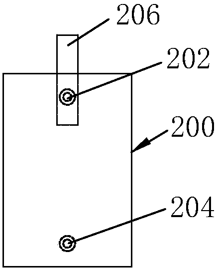
[0062] image 3 and Figures 3A-3F Shown is a third embodiment of the invention. The main difference between the third embodiment and the first embodiment is: A) the isolation tank 200 is placed vertically (of course it can also be placed inclined, but the effect is better when placed vertically); B) the liquid inlet 202 of the isolation tank is located at On the top wall 203 of the isolation tank, the liquid outlet 204 of the isolation tank is positioned at the bottom of the side wall 207 of the isolation tank or on the bottom wall 205; C) the device 206 for controlling the liquid flow rate is a disc shape (such as Figure 3D shown) or a conical structure (such as Figure 3A shown). At this time, the disc-shaped or cone-shaped structure is fixed on the inner wall of the isolation pool, and a gap is designed between the edge of the disc-shaped or cone-shaped structure and the inner wall 207 of the isolation pool to allow liquid to pass through. like Figure 3B As shown, t...


PUM

PropertyMeasurementUnit
diameteraaaaaaaaaa

Abstract

The invention relates to an isolation cell for a sheath flow impedance counting device. The isolation cell comprises a container body, an inner cavity, a liquid inlet and a liquid outlet, wherein a device for controlling the flow velocity of liquid is arranged at and connected with the liquid inlet of the isolation cell. The device for controlling the flow velocity of liquid is arranged at or nearthe liquid inlet of the isolation cell to effectively decelerate liquid flowing out from the liquid inlet, so the flow velocity of fed liquid touching the inner wall or bottom liquid level of the isolation cell is much smaller than the flow velocity of the liquid just flowing out from the liquid inlet, and impact of the fed liquid on the inner wall or bottom liquid level of the isolation cell isreduced; and thus, the probability of generation of bubbles is lowered, interference of bubbles to a counter is decreased, and the accuracy of instrument testing is improved.

Description

technical field [0001] The invention relates to a sheath current impedance counting device, in particular to an isolation pool applied to the sheath current impedance counting device. technical background [0002] Sheath flow impedance counting is a commonly used technique in flow hematology analyzers. The sheath flow impedance counter is usually composed of three parts: the front pool, the back pool, and the counting hole between the front and back pools. Among them, there is an electrical signal between the solutions in the fore cell and the back cell. When the particles in the solution pass through the counting hole between the front and rear cells, the electrical signal will change, so the front and rear cells need to be isolated, usually the rear cell. [0003] The current technology basically adopts the method of air isolation, that is, there is a back pool isolation tank between the back pool liquid inlet and the liquid storage tank, the liquid first drips into the ...

Claims


Application Information

Patent Timeline
Patent Type & Authority Applications(China)
IPC IPC(8): G01N15/14
CPCG01N15/1404G01N2015/0065G01N2015/1006G01N2015/1409G01N2015/1486
Inventor 张学锋武林管海兵徐伟
Owner LEADWAY HK
Why Eureka
Try Eureka