Dynamic detection system and method for geometric parameters of vehicle-mounted non-contact overhead line system

A geometric parameter and dynamic detection technology, applied in the field of detection, can solve the problems of complex structure, difficult installation, low precision, etc., and achieve the effect of high detection precision, simple structure and wide versatility

Active Publication Date: 2018-02-09
株洲嘉成科技发展股份有限公司
View PDF8 Cites 18 Cited by
  • Summary
  • Abstract
  • Description
  • Claims
  • Application Information

AI Technical Summary

Problems solved by technology

[0004] (1) Using contact detection, it is difficult to install, complex in structure and low in precision;
[0005] (2) Using a non-contact single sensor, the detection effect is poor and the accuracy is low;
[0006] (3) There is no vehicle body vibration compensation, or the vehicle body vibr

Method used


Image

  • Dynamic detection system and method for geometric parameters of vehicle-mounted non-contact overhead line system
  • Dynamic detection system and method for geometric parameters of vehicle-mounted non-contact overhead line system
  • Dynamic detection system and method for geometric parameters of vehicle-mounted non-contact overhead line system

Examples


Embodiment 1

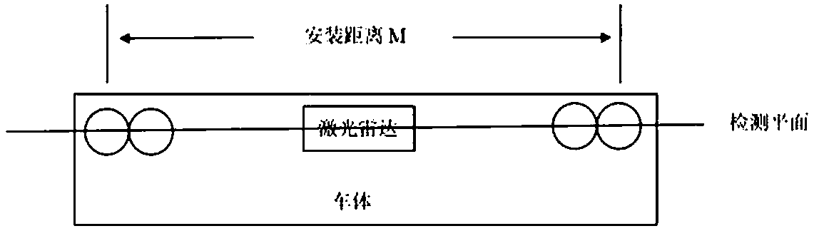
[0035] This embodiment provides a vehicle-mounted non-contact type catenary geometric parameter dynamic detection system. Such as figure 1 As shown, it includes a geometric detection unit located on the top of the vehicle body for detecting the contact net, a control unit provided inside the vehicle body, and a vibration compensation unit located on the bottom of the vehicle body for detecting vibration of the vehicle body.

[0036] The vibration compensation unit is located at the bottom of the vehicle and is composed of two two-dimensional contour scanning sensors; and the geometric detection unit and the vibration compensation unit are installed in the same cross section of the vehicle body perpendicular to the rail.

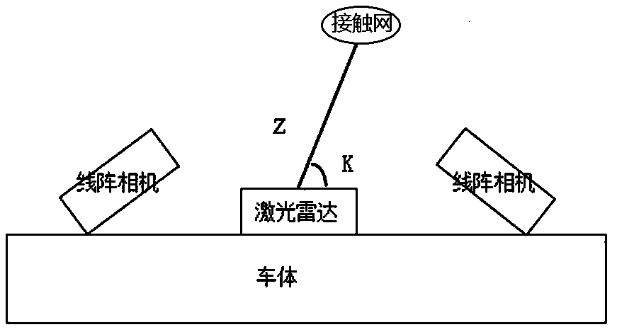
[0037] Such as figure 2 , image 3 As shown, the geometric detection unit is located in the center of the car body and includes a lidar and four line array cameras, a light source and a mounting bracket. The lidar and line scan cameras are installed on the top of ...

Embodiment 2

[0042] This embodiment provides a detection method to which Embodiment 1 is applied.

[0043] It includes the following steps:

[0044] S1. Use lidar and line array camera to detect the spatial position of the catenary on the roof of the vehicle.

[0045] Before the actual inspection, calibrate the line scan camera, the process is as follows.

[0046] S11. Use regression technology to calibrate the line scan camera used to measure the catenary in advance.

[0047] S111 Obtain training data, and obtain the correspondence between world coordinates and pixel coordinates of the line array camera;

[0048] In the calibration process, usually an object with known spatial position information is used as a scene for shooting, such an object is called a calibration object. In this embodiment, a black strip is used as a calibration object, and the shooting is performed from several visions. Considering that the target surface of the line scan camera is relatively large, and in order to make the ...


PUM


Abstract

The invention relates to the technical field of measurement, and discloses a dynamic detection system and method for geometric parameters of a vehicle-mounted non-contact overhead line system. The detection system comprises a geometric detection unit which is arranged at the vehicle roof and used for detecting the overhead line system, a control unit arranged in a vehicle body and a vibration compensation unit which is arranged at the vehicle bottom and used for detecting vibration of the vehicle body, and is characterized in that the geometric detection unit comprises laser radar, linear array cameras and light sources; the laser radar is arranged at the center of the geometric detection unit; two groups of the linear array cameras are set, each group comprises two linear array cameras, the two groups of the linear array cameras are respectively arranged at two sides of the laser radar, and the linear array cameras in the same group are obliquely arranged relative to the vehicle roof;the laser radar and the linear array cameras are distributed at the same straight line, a scanning area of the laser radar and a detection area of the linear array cameras are located at the same detection plane; and the light sources are arranged at two sides of the laser radar. The detection system and method are high in detection precision, simple in structure and easy to install.

Description

Technical field [0001] The invention relates to the field of detection technology, and more specifically, to a vehicle-mounted non-contact type catenary geometric parameter dynamic detection system and method. Background technique [0002] The catenary is a high-voltage transmission line that is erected in a zigzag pattern over the rails in an electrified railway for the pantograph. Good contact between the contact wire and the pantograph is the key to ensure the quality of the electric locomotive. With the rapid development of China's railway industry and the continuous increase of electrified railway mileage, the intensity and difficulty of overhauling the catenary are increasing. In order to increase the speed of fault detection and ensure the safe operation of the line, it is particularly urgent to develop a high-speed and high-precision contact line detection equipment. In July 2012, the Railway Corporation launched the "General Technical Specification for High-speed Rail...

Claims


Application Information

Patent Timeline
IPC IPC(8): G01S17/02G01S17/48G01S7/497
CPCG01S7/4972G01S17/48G01S17/86
Inventor 邹春富弘毅陈俊峰胡辉廖小路廖展
Owner 株洲嘉成科技发展股份有限公司
Why Eureka
Try Eureka