Image acquiring and splicing method used for large-scale micro-imaging area

A microscopic imaging and imaging area technology, applied in image data processing, graphics and image conversion, instruments, etc., can solve problems such as time-consuming and labor-intensive, non-conforming images, lack of concentration, etc., achieve high quality, improve image stitching efficiency and Accuracy, cost reduction effect

Inactive Publication Date: 2018-02-09
UNIV OF ELECTRONICS SCI & TECH OF CHINA
View PDF3 Cites 8 Cited by
  • Summary
  • Abstract
  • Description
  • Claims
  • Application Information

AI Technical Summary

Problems solved by technology

In the actual situation: it is not only time-consuming and labor-intensive to take images manually through a microscope, but also there are many uncontrollable factors. For example, it is difficult for the photographer to control the length under the microscope. Personnel may also be distracted due to fatigue, so that the captured images do not meet the requirements; if the traditional method is used to control the platform to move with a specified step size and then take pictures, due to the small field of view, the accuracy of ordinary transmission gears cannot be achieved when the platform moves. Meet the above requirements: the size of the overlapping area is relatively random, and there may be no overlapping area after the microscope platform moves for many times
The image taken in this way cannot complete the image stitching

Method used


Image

  • Image acquiring and splicing method used for large-scale micro-imaging area

Examples


Embodiment Construction

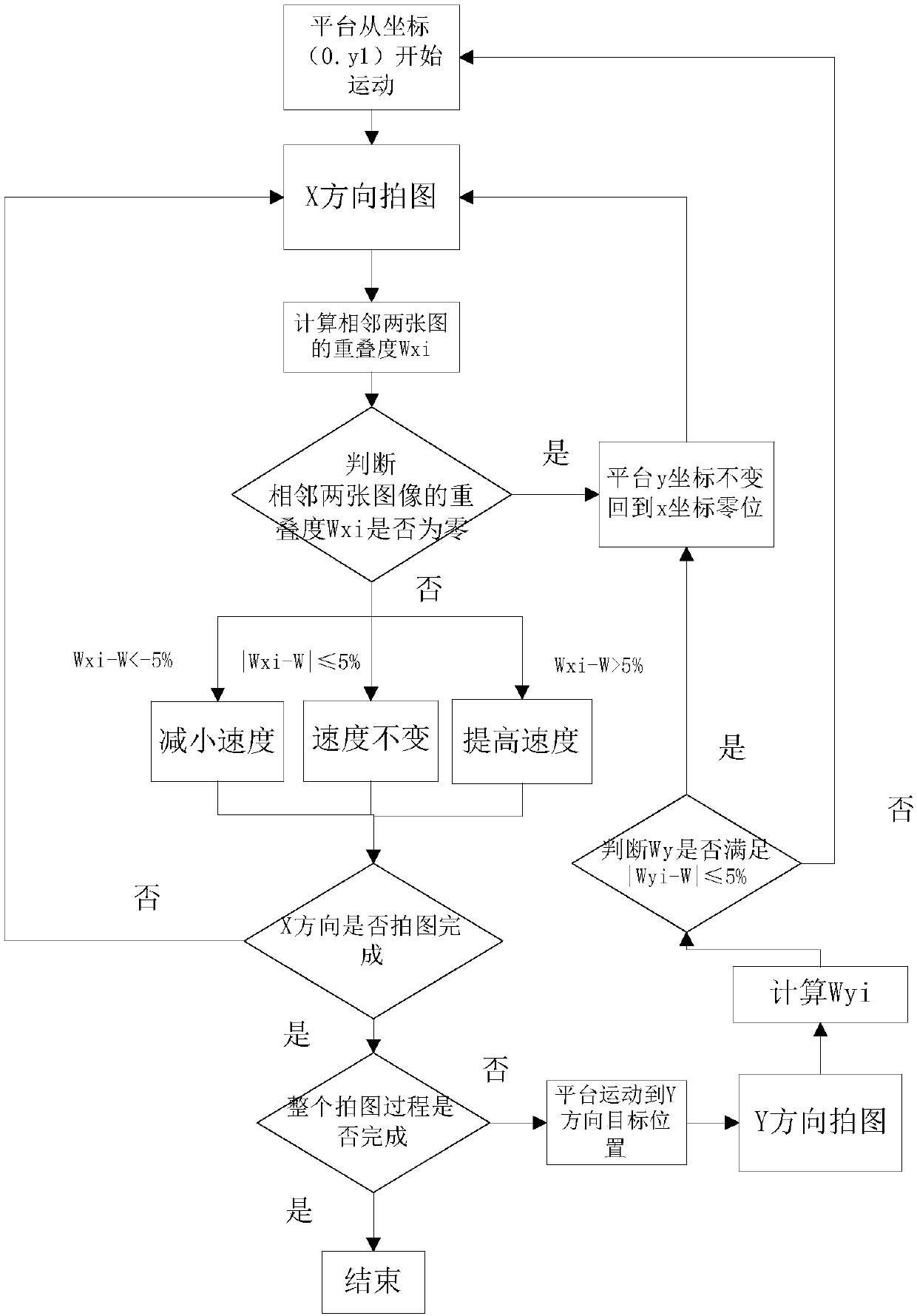
[0016] Step 1: First determine the rectangular imaging area that needs microscopic imaging, set the length in the X direction to 4cm, the length in the Y direction to 2cm, and the field of view of the microscope is X in the X direction. cx =0.4cm, Y direction Y cy =0.3cm, the best overlapping area W when splicing images (the range of W can be 10%-20%). Adjust the position of the imaging area so that most of the first image taken by the microscope is a rectangular imaging area. Start moving at the speed Vx=0.36cm / s in the X direction, and the sampling rate of the camera is 1Hz (as long as the distance between the moving speed of the platform and the photographing speed of the camera satisfies theoretically, between two consecutive photographs of the camera, the length of the platform movement is the field of view of the microscope Nine-tenths of the length is sufficient).

[0017] Step 2: Acquire the first image from the zero position, set the position of the first image to (...


PUM


Abstract

The invention discloses a real time image splicing method used for a low-precision micro-imaging system, relates to an image snap method for a microscope and specifically relates to an image snap method for image splicing technology in automatic snap of the microscope. The invention solves a problem of low positioning precision in traditional image snap and improves reliability and quality of acquisition of spliced images with a low cost, reduces cost of a positioning device in an image acquiring process and improves image splicing efficiency and accuracy.

Description

technical field [0001] The invention relates to a method for taking pictures under a microscope, specifically, a method for taking pictures used in the image stitching technology for automatically taking pictures under a microscope. Background technique [0002] Such a process exists in automatic detection equipment such as blood, feces, and urine: the camera takes pictures of the sample through a microscope, obtains images of multiple fields of view of the sample, and then performs image processing on the images of each field of view to detect the interesting ones. Components, and finally unify the detection results of all fields of view to give the final conclusion. Due to the need to take images of multiple fields of view, the formed elements of interest such as white blood cells, epithelial cells, etc., especially the formed elements of tubular structures or long strip structures, may only have a part in the captured field of view, and the other part in the adjacent In ...

Claims


Application Information

Patent Timeline
Patent Type & Authority Applications(China)
IPC IPC(8): G06T3/40
CPCG06T3/4038
Inventor 刘霖田济铭夏翔陆宋晗钟亚张静刘娟秀倪光明杜晓辉刘永
Owner UNIV OF ELECTRONICS SCI & TECH OF CHINA
Why Eureka
Try Eureka