Panoramic video splicing method

A panoramic video and scene video technology, applied in the field of panoramic video stitching, can solve the problems of high error matching rate and low matching degree of feature points, and achieve the effect of improving stitching efficiency

Inactive Publication Date: 2017-06-13
ZHEJIANG DETU NETWORK CO LTD
View PDF3 Cites 12 Cited by
  • Summary
  • Abstract
  • Description
  • Claims
  • Application Information

AI Technical Summary

Problems solved by technology

[0002] Video stitching technology refers to the technology of splicing video images collected by several cameras to form a panoramic image. Most of the commonly used video stitching technologies are based on image stitching algorithms to find the overlapping parts of adjacent video images for conversion and stitching. However, this method is affected by factors such as changes in the camera scene, different shooting angles, and stitching algorithms.
And the panoramic camera is a fisheye lens, and the obtained image is a fisheye image with distortion. If the feature points are extracted directly, the matching degree of the extracted feature points is very low, and the false matching rate is high.

Method used


Image

  • Panoramic video splicing method
  • Panoramic video splicing method
  • Panoramic video splicing method

Examples


Embodiment 1

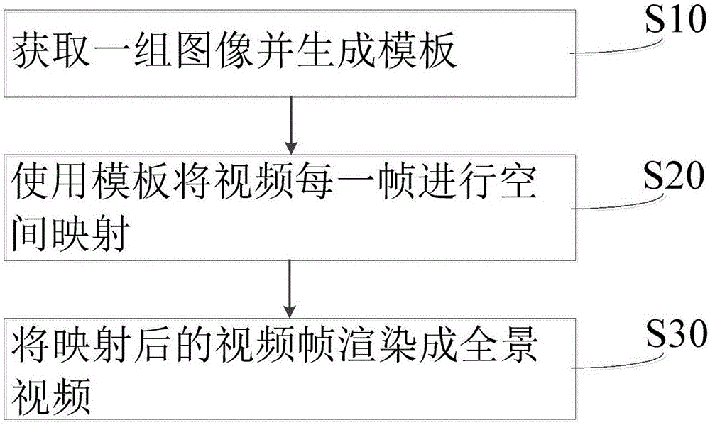
[0041] see figure 1 , is a flow chart of the steps of the panoramic video stitching method in a specific embodiment of the present invention, comprising the following steps:

[0042] S10, acquiring a set of images and generating a template;

[0043] S20, using a template to spatially map each frame of the video;

[0044] S30. Render the mapped video frame into a panoramic video.

[0045] Through the above steps, a group of images to be spliced ​​can be generated as a template, and the generated template is a set of parameters, which are the mapping parameters for mapping the circumferential fisheye image to the final equidistant cylindrical image (ie, the panoramic image). Using the template, each frame of the video can be spatially mapped and then rendered into a panoramic video. The generated template can directly stitch the video images captured by the subsequent panoramic camera, which greatly improves the efficiency.

Embodiment 2

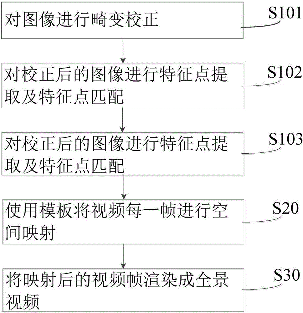
[0047] see figure 2 , is a flow chart of the steps of the panoramic video stitching method in a specific embodiment of the present invention, comprising the following steps:

[0048] S101, performing distortion correction on the image;

[0049] S102, performing feature point extraction and feature point matching on the corrected image;

[0050] S103, using the optimization algorithm and the feature point matching result to estimate the spatial mapping parameters, and saving the mapping parameters as a template;

[0051] S20, using a template to spatially map each frame of the video;

[0052] S30. Render the mapped video frame into a panoramic video.

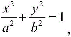
[0053] In the above steps, S101 performs distortion correction on the image, using the latitude and longitude correction method. On a certain longitude, the elliptic equation of a point on the image is:

[0054]

[0055] The coordinates after latitude and longitude correction are (x1, y1), and the correction relationship ...


PUM


Abstract

The invention discloses a panoramic video splicing method. The method comprises the steps of obtaining a set of images and generating a template; adopting the template for performing space mapping on each frame of a video; rendering the mapped video frames into a panoramic video, wherein the step of generating the template comprises the substeps of performing distortion correction on the images; performing feature point extraction and feature point matching on the corrected images; adopting an optimization algorithm and a feature point matching result for estimating space mapping parameters and storing the mapped parameters into the template. In order to obtain more extracted feature points and make extracted feature points to be more accurate, the distortion phenomenon of a panoramic fisheye video camera is eliminated through distortion correction; follow-up video images are directly used after the template is generated, regeneration is not needed, and the splicing efficiency is improved.

Description

technical field [0001] The invention belongs to the technical field of video processing, and relates to a panoramic video splicing method. Background technique [0002] Video stitching technology refers to the technology of splicing video images collected by several cameras to form a panoramic image. Most of the commonly used video stitching technologies are based on image stitching algorithms to find the overlapping parts of adjacent video images for conversion and stitching. However, such methods are affected by factors such as changes in the camera scene, different shooting angles, and stitching algorithms. And the panoramic camera is a fisheye lens, and the obtained image is a fisheye image, which has distortion. If the feature points are extracted directly, the matching degree of the extracted feature points is very low, and the false matching rate is high. Contents of the invention [0003] In order to solve the above problems, the object of the present invention is...

Claims


Application Information

Patent Timeline
Patent Type & Authority Applications(China)
IPC IPC(8): G06T3/40G06T7/73G06T7/55
Inventor 涂植跑孙其瑞郑宇斌李昌岭胡正东
Owner ZHEJIANG DETU NETWORK CO LTD
Why Eureka
Try Eureka