An inverter capacitor clamping device

A clamping device and capacitor technology, applied in the direction of capacitors, electrical components, etc., can solve the problems that inverter capacitors cannot quickly adjust the clamping tightness of external clamping parts, the external connection of capacitors is not stable enough, and cannot meet the needs of users. , to achieve the effect of stable connection, convenient connection and flexible mobile card connection

Active Publication Date: 2019-05-24
铜陵正豪科技有限公司
View PDF5 Cites 0 Cited by
  • Summary
  • Abstract
  • Description
  • Claims
  • Application Information

AI Technical Summary

Problems solved by technology

[0002] With the rapid development of electronic information technology, the upgrading speed of digital electronic products is getting faster and faster. The production and sales of consumer electronic products, mainly flat-panel TVs (LCD and PDP), notebook computers, digital cameras and other products, continue to grow. The capacitor industry is growing, but inverter capacitors cannot quickly adjust the clamping tightness of the entire external clamping parts, and the external connection of the entire capacitor is not stable enough, and the connection method is relatively simple, which cannot meet the needs of users.

Method used


Image

  • An inverter capacitor clamping device
  • An inverter capacitor clamping device
  • An inverter capacitor clamping device

Examples


Embodiment 1

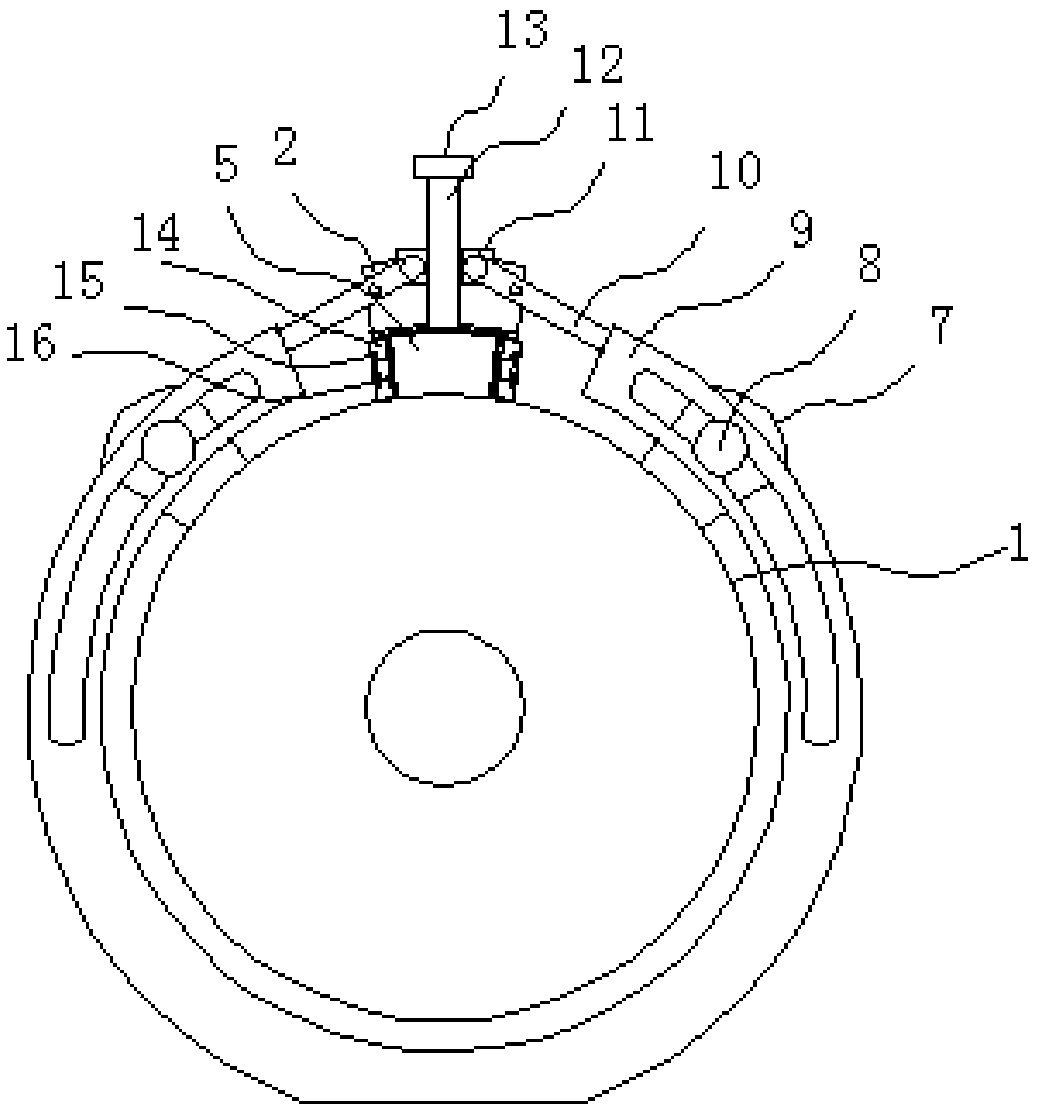
[0016] Example 1: Reference figure 1 , A graded dry inverter capacitor, comprising a body shell 1, a sliding plate 5 is arranged above the body shell 1, a sliding seat 2 is clamped on the sliding plate 5, and two ends of the sliding seat 2 are provided with limit grooves, the sliding seat 2 is provided with a sliding groove that matches with the sliding plate 5, and the upper side of the sliding seat 2 is provided with a rotating groove. The end is provided with a first groove, a connecting rod 10 is rotatably connected in the first groove, a clamping ring 9 is connected to the end of the connecting rod 10 away from the slip ring 11, and a limit seat 7 is symmetrically provided on both sides of the body shell 1. One side of the holding ring 9 is provided with a limiting post 8, one side of the clamping ring 9 is provided with a limiting opening for clamping the limiting post 8, the other end of the threaded rod 12 is connected with a first rotating block 13; the sliding seat 2 ...

Embodiment 2

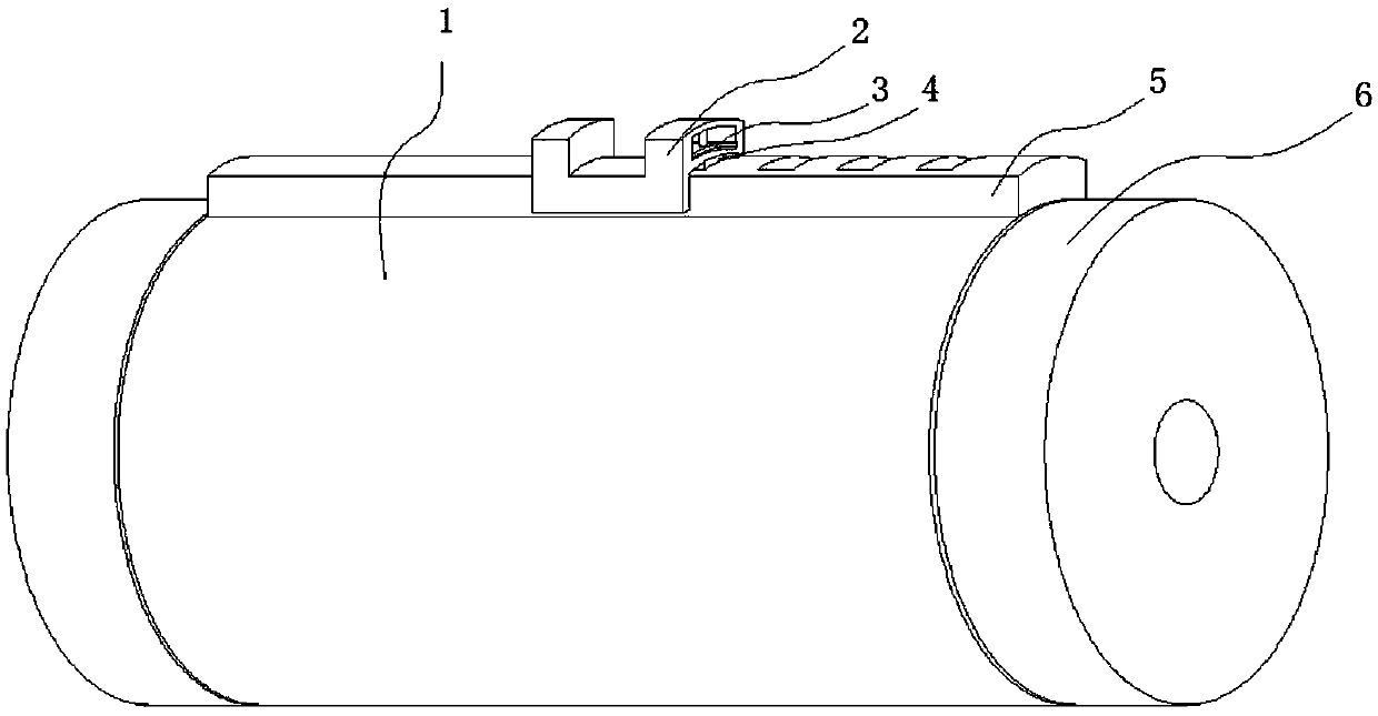
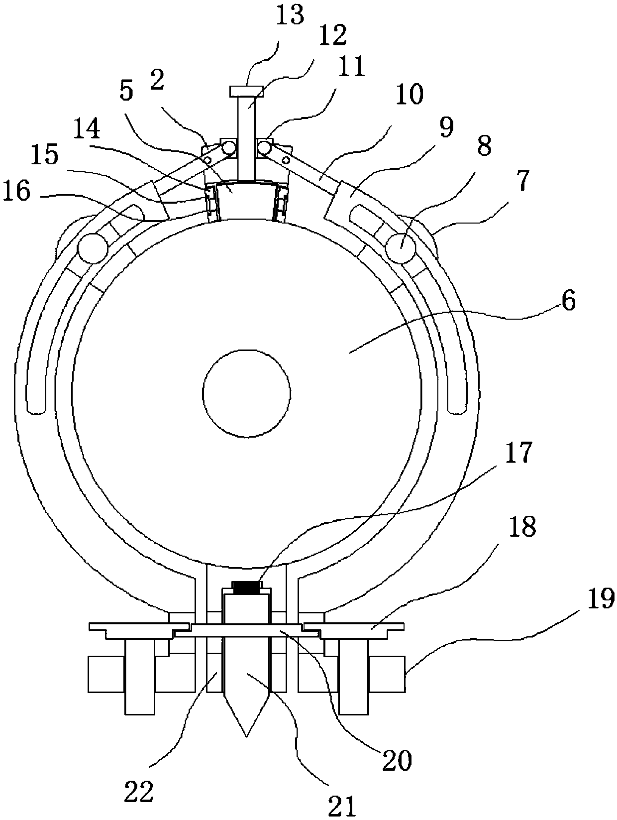
[0017] Example 2: Reference Figure 2-4 , The present invention is applied to a graded dry inverter capacitor, including a body shell 1, a sliding plate 5 is arranged above the body shell 1, a sliding seat 2 is clamped on the sliding plate 5, and both ends of the sliding seat 2 are provided with limit Slot, under the sliding seat 2 is provided with a sliding slot matched with the sliding plate 5, the bottom of the limit slot is provided with a socket communicating with the sliding slot, a plug 4 is inserted in the socket, and a limit plate 3 is arranged in the inner slot in the afternoon , One end of the insert block 4 is connected to the limit plate 3, the upper part of the sliding plate 5 is provided with a slot for clamping one end of the insert block 4, the upper part of the sliding seat 2 is provided with a rotating groove, and the bottom of the rotating groove is rotatably connected with a threaded rod 12. A slip ring 11 is sleeved on the threaded rod 12, the two ends of ...


PUM


Abstract

The invention discloses an inversion capacitor clamping apparatus. The inversion capacitor clamping apparatus comprises a capacitor shell; a sliding plate is arranged above the capacitor shell; a sliding base is clamped on the sliding plate; limiting grooves are formed in the two ends of the sliding base; a sliding groove matched with the sliding plate is formed below the sliding base; a rotary groove is formed above the sliding base; the bottom of the rotary groove is rotationally connected with a threaded rod; the threaded rod is sleeved with a slip ring; first grooves are formed in the twoends of the slip ring; and connecting rods are rotationally connected in the first grooves. By virtue of the whole inversion capacitor clamping apparatus, connection between a clamping ring and the capacitor shell can be adjusted by a user conveniently; and in addition, by virtue of movement of the slip ring, movable clamping connection is realized, so that connection between a capacitor applyingthe inversion capacitor clamping apparatus and the external can be more stable.

Description

Technical field [0001] The invention relates to the technical field of inverter capacitors, in particular to an inverter capacitor clamping device. Background technique [0002] With the rapid development of electronic information technology, the update speed of digital electronic products is getting faster and faster. The production and sales of consumer electronic products such as flat-panel TVs (LCD and PDP), notebook computers, digital cameras and other products continue to grow, which has driven The capacitor industry is growing, but inverter capacitors cannot quickly adjust the clamping tightness of the entire external clamping piece, and the external connection of the entire capacitor is not stable enough, and the connection method is relatively single, which cannot satisfy users. Summary of the invention [0003] Based on the technical problems existing in the background art, the present invention proposes an inverter capacitor clamping device. [0004] A clamping device fo...

Claims


Application Information

Patent Timeline
Patent Type & Authority Patents(China)
IPC IPC(8): H01G2/02H01G2/04
CPCH01G2/02H01G2/04
Inventor 舒均褚诗泉李义纪沿海
Owner 铜陵正豪科技有限公司
Why Eureka
Try Eureka