Auto-Injector With A System For Delaying The Device Indicating The Removal Of The Auto-Injector

A technology of automatic injector and time-delay system, which is applied in the field of automatic injector, and can solve problems such as interference, non-compliance with requirements, unsafe and reliable, etc.

Active Publication Date: 2018-02-09
APTAR FRANCE SAS
View PDF10 Cites 2 Cited by
  • Summary
  • Abstract
  • Description
  • Claims
  • Application Information

AI Technical Summary

Problems solved by technology

Therefore, it is not safe, reliable or desirable as the system is user dependent and in some cases the user may be disturbed or overwhelmed by the injection he or she is performing

Method used


Image

  • Auto-Injector With A System For Delaying The Device Indicating The Removal Of The Auto-Injector
  • Auto-Injector With A System For Delaying The Device Indicating The Removal Of The Auto-Injector
  • Auto-Injector With A System For Delaying The Device Indicating The Removal Of The Auto-Injector

Examples


Embodiment Construction

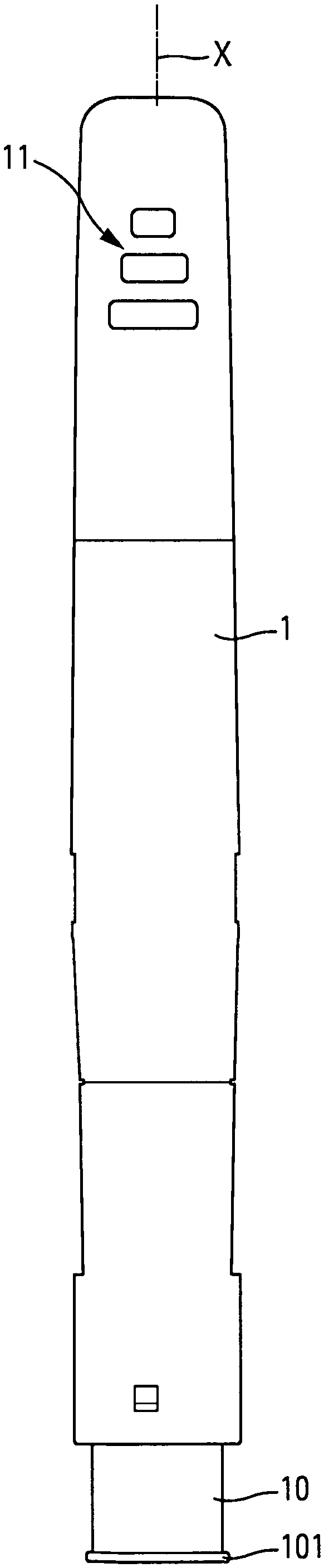
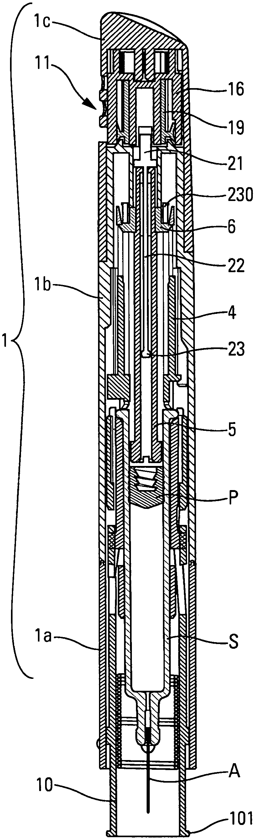
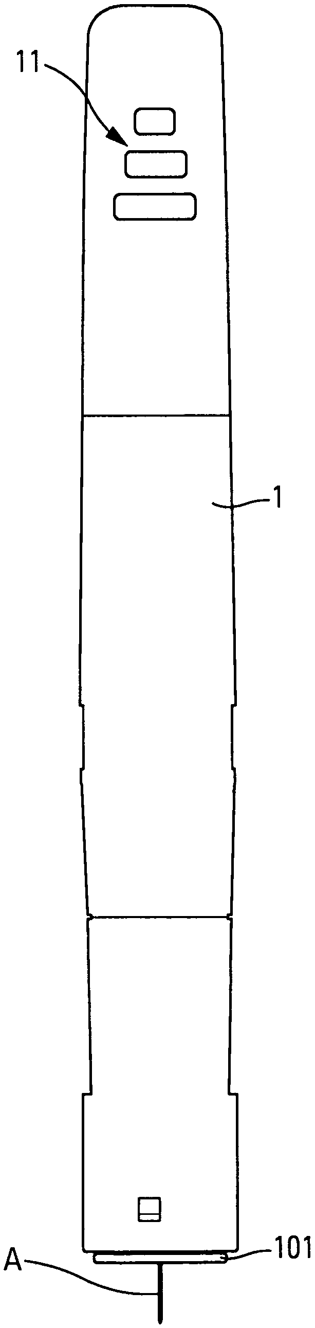
[0064] In the following description, the terms "upper", "lower", "higher" and "lower" refer to Figure 1a to Figure 6 , Figure 15 , Figure 20a to Figure 26 and Figure 34 location shown. The terms "axial" and "radial" especially refer to Figure 1a and Figure 20a A central longitudinal axis X is shown, which corresponds to the longitudinal axis of the needle.

[0065] The autoinjector will be described below with reference to two advantageous embodiments. It should be noted, however, that autoinjectors are complex instruments comprising multiple components for performing multiple functions. These various components are used individually and independently of each other without the need for combination with other components, especially for auto-injectors of different shapes than those shown in the figures. In addition, it should be noted that the drawings are schematic and, particularly for the sake of clarity, do not necessarily show the exact shapes of the autoinjecto...


PUM


Abstract

An auto-injector comprising: - a body (1) receiving a reservoir (S), said reservoir (S) containing fluid product and comprising a piston (P), in the same way as a pre-filled syringe, - a piston rod (5) suitable for cooperating with the piston (P) of said reservoir (S), said piston rod (5) being movable between a loaded position and an injection position in which said piston rod (5) has moved the piston (P) of the reservoir (S) in order to inject the fluid product into an injection site, - a visual, audio and / or tactile indicator device, for indicating to the user that he can remove said auto-injector from said injection site, said auto-injector comprising a delay system for delaying the actuation of said visual, audio and / or tactile indicator device relative to the end of the injection, said delay system comprising a reservoir (16), a shear member (19) disposed in said reservoir (16) and a fluid disposed in said reservoir (16) around said shear member (19), one of said reservoir (16) and said shear member (19) being mounted rotating in said body (1) and the other of said reservoir (16) and said shear member (19) being fixed in rotation, the rotation of one relative to the other being braked by the shearing of said fluid contained in said reservoir (16), said reservoir (16) comprising projections (165) on the inner surface of same and said shear member (19) comprising projections (195) on the outer surface of same, said projections (165, 195) generating restrictions to the flow of the fluid.

Description

technical field [0001] The present invention relates to an automatic injector. Background technique [0002] Autoinjectors are well known in the art. These devices are primarily used to automatically inject the contents of a syringe into a patient. Various systems exist for automatically piercing a needle into a patient and infusing a fluid contained in a syringe. Autoinjectors are relatively complex devices that must accommodate many constraints that increase safety and reliability. The robustness of the device, its ease of handling and its ease of use for the user are also important factors. In addition, most of these auto-injectors are disposable, and the production cost and assembly cost should also be considered factors. [0003] There are many auto-injectors on the market, however, which have a number of drawbacks. [0004] Therefore, especially when the fluid volume is large, and / or when the injected fluid is thick, it is desirable to be able to disperse the flui...

Claims


Application Information

Patent Timeline
IPC IPC(8): A61M5/315A61M5/20A61M5/32
CPCA61M5/2033A61M5/3157A61M5/326A61M2205/581A61M2205/582A61M2205/583A61M2005/2013A61M2005/2086A61M2205/43
Inventor D·法比恩T·戈麦兹O·伊斯A·索赛
Owner APTAR FRANCE SAS
Why Eureka
Try Eureka