Bone plate

A bone plate and bone technology, applied in the medical field, can solve the problems of dislocation of the embracing arm, inability to effectively fix the sternum, falling off, etc., and achieve the effect of not easily falling off, not easy to slide, and enhancing the retention effect.

Pending Publication Date: 2018-02-13
SHANGHAI XINCHANG MEMORY ALLOY TECH
View PDF3 Cites 2 Cited by
  • Summary
  • Abstract
  • Description
  • Claims
  • Application Information

AI Technical Summary

Problems solved by technology

[0004] The problem to be solved by the present invention is that in the existing methods of embracing and fixing the sternum, the embracing arm

Method used


Image

  • Bone plate
  • Bone plate
  • Bone plate

Examples


no. 1 example

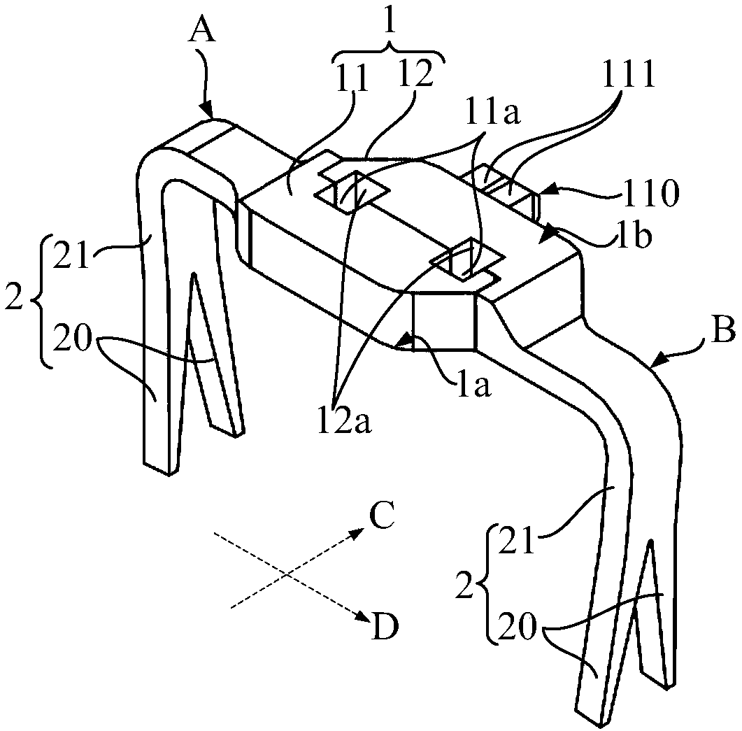
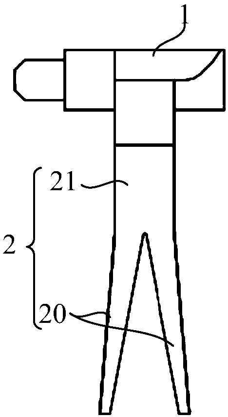
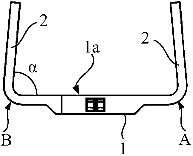
[0040] refer to figure 1 , The bone plate includes: a bone positioning part 1, which has a bone positioning surface 1a conforming to the shape of the site to be boned and an upper surface 1b facing away from the bone positioning surface 1a. Two ends A and B of the bone positioning part 1 are respectively provided with insertion arms 2, the insertion arms 2 extend away from the upper surface 1b, so that the insertion arms 2 and the bone positioning surface 1a are on the same side, and the insertion arms 2 are used to insert the bone to be fused.

[0041] In application, the bone positioning part 1 matches the shape of the part to be boned so that the bone positioning surface 1a is close to the part to be boned. The plate is fixed on the bone to be set, and the insertion arms 2 at the two ends A and B form a clamping force on the bone to be set from both sides, and the clamping force can gradually heal the bone to be set. After the bone-synthesis site is healed, the insertion a...

no. 2 example

[0075] Compared with the first embodiment, the second embodiment differs in that:

[0076] First, refer to Figure 6 and combine Figure 7 , the first sub-positioning portion 31 is provided with a first insert 310 and a second accommodation space 311, and the first insert 310 and the second accommodation space 311 are separated from each other. The second sub-positioning portion 32 is provided with a first receiving space 321 and a second insert 320 , and the second insert 320 and the first receiving space 321 are separated from each other.

[0077] When the first insert 310 is inserted into the first accommodation space 321 along the first direction CC, the second insert 320 is inserted into the second accommodation space 311 along the first direction CC, and the first sub-positioning part 31 and the second sub-positioning There are 2 plugging positions between the parts 32 . Compared with one insertion position, the two insertion positions can make the connection between ...

no. 3 example

[0080] Compared with the second embodiment, the third embodiment differs in that:

[0081] refer to Figure 8 The upper surface 4b of the first sub-positioning part 41 is provided with a first receiving part 410 and the upper surface 4b of the second sub-positioning part 42 is provided with a second receiving part 420, and the side wall of the first receiving part 410 circles around to form a closed The side wall surrounds the first accommodating portion 410 , and the side wall of the second accommodating portion 420 circles around to form a closed side wall to enclose the second accommodating portion 420 . Therefore, in combination with the solution of the first embodiment, when the two sub-positioning parts have opposite sides along the first direction CC, the side wall of at least one accommodating part can go around for a circle; or, at least one accommodating part can have a The notch on the side of the head.

[0082] Both the first accommodating portion 410 and the sec...


PUM


Abstract

A bone plate comprises a skeleton positioning part. The skeleton positioning part is provided with a skeleton positioning surface in a shape matched with the shape of a to-be-jointed part and an uppersurface which is opposite to the skeleton positioning surface; insertion arms are arranged at the two ends of the skeleton positioning part, the insertion arms extend in opposite to the upper surfaceand used for inserting a to-be-jointed bone. In use, the shape of the skeleton positioning part is matched with that of the to-be-jointed part so as to make the skeleton positioning surface attachedto the to-be-jointed part; the insertion arms at the two ends of the skeleton positioning part are inserted and clamped into the to-be-jointed bone so as to make the bone plate fixed to the to-be-jointed bone; the insertion arms at the two ends apply clamping pressure on the to-be-jointed part, and the to-be-jointed part can heal gradually due to the clamping pressure. Compared with the prior art,the to-be-jointed bone is inserted by using the insertion arms so that the immobilization effect between the bone plate and the to-be-jointed bone can be enhanced, and the bone plate is not likely toslide on the to-be-jointed bone or fall off from the to-be-jointed bone.

Description

technical field [0001] The invention relates to the field of medical technology, in particular to a bone plate. Background technique [0002] At present, there are many methods for sternotomy and sternal fracture fixation clinically, including steel wire fixation and titanium plate and titanium nail fixation. Wire binding fixation is to use steel wire to bind the sternum, and titanium plate and titanium nail fixation is to use titanium nails to pass through the titanium plate and nail into the sternum, and the titanium plate fixes the sternum. However, these methods inevitably have defects. For example, for elderly patients, especially those with severe osteoporosis, it is not advisable to drill too many holes in the sternum, which limits the application of titanium plate and titanium nail fixation; The case of cutting the sternum. Therefore, at present, memory alloy bone plates are used to fix the sternum. The bone plate is integrally formed with two sets of arms that are...

Claims


Application Information

Patent Timeline
IPC IPC(8): A61B17/80
CPCA61B17/8076A61B17/808
Inventor 不公告发明人
Owner SHANGHAI XINCHANG MEMORY ALLOY TECH
Why Eureka
Try Eureka