
Novel automatic attaching robot

A crimping machine and automatic buckle technology, which is applied to metal processing equipment, feeding devices, positioning devices, etc., can solve the problems of not installing rotating handles and anti-slip sleeves, making it difficult to hide and use pulleys, and not being convenient for fixing metal joints. Achieve the effects of avoiding inconvenient movement, convenient movement and maintenance, and easy fixation

Inactive Publication Date: 2018-02-13
北海南坡腕网络技术有限公司
View PDF0 Cites 2 Cited by
  • Summary
  • Abstract
  • Description
  • Claims
  • Application Information

AI Technical Summary

Problems solved by technology

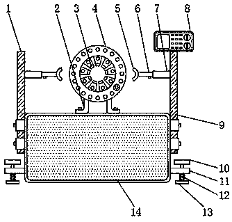
[0004] The present invention provides a new type of automatic crimping robot, which can effectively solve the problems mentioned above in the background technology that there is no electro-hydraulic rod, which makes it difficult for users to hide and use the pulley, and there is no rotating handle and anti-slip sleeve, which makes it difficult for users to rotate and rotate. The handle makes the anti-slip sleeve contact the contact surface, and there is no telescopic rod and support plate, which makes it difficult for users to fix the metal joint

Method used

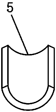
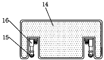

Image

  • Novel automatic attaching robot
  • Novel automatic attaching robot
  • Novel automatic attaching robot

Examples


Embodiment Construction

[0022] The preferred embodiments of the present invention will be described below in conjunction with the accompanying drawings. It should be understood that the preferred embodiments described here are only used to illustrate and explain the present invention, and are not intended to limit the present invention.

[0023] Example: such as Figure 1-4 As shown, the present invention provides a technical solution, a novel automatic crimping robot, comprising a crimping machine body 14 and a fixed mold 4, one side of the crimping machine body 14 is provided with a second support frame 9, and the other side of the crimping machine body 14 One side is provided with the first support frame 1, and one side of the crimping machine body 14 is provided with a fixed rod 11 near the position below the second support frame 9, and the top of the crimping machine body 14 is provided with a bracket 2, and the inside of the crimping machine body 14 An electro-hydraulic rod 16 is embedded, and ...


PUM


Abstract

The invention discloses a novel automatic crimping robot, which comprises a crimping machine body and a fixed mold. An electro-hydraulic rod is embedded inside the crimping machine body, and a crimping machine body is sleeved near the bottom end of the electric hydraulic rod. Pulley, one side of the support rod is embedded with a telescopic rod, one end of the telescopic rod is sleeved with a support pulley, the top end of the threaded rod is provided with a rotating handle, and the bottom end of the threaded rod is provided with an anti-slip sleeve. The invention is equipped with an electro-hydraulic rod, which can facilitate the user to hide and use the pulley, and a rotating handle and an anti-slip sleeve are provided, which can facilitate the user to make the anti-slip sleeve contact with the contact surface by rotating the rotating handle, thereby increasing the transportation process of the crimping machine body In terms of stability and safety, the telescopic rod and support plate are set, which can facilitate the user to fix the metal joints, and avoid the problem that the user's fingers touch the movable mold and cause dangerous situations.

Description

technical field [0001] The invention relates to the technical field of robot production, in particular to a novel automatic crimping robot. Background technique [0002] The crimping machine is a kind of hydraulic equipment used for crimping the pipe fitting assembly. It applies shrinkage force to the matching metal joint through the mold of the crimping machine, and firmly crimps the metal joint on the high-pressure oil pipe for the supporting construction machinery or the car. Brake pipes, engine oil pipes, air conditioning pipes, and power pipes. [0003] However, the crimping machines currently on the market have complex structures and single functions. There is no electro-hydraulic rod, which makes it difficult for users to hide and use the pulley. It is in contact with the contact surface, and there is no telescopic rod and support plate, which cannot facilitate the user to fix the metal joint. Contents of the invention [0004] The present invention provides a new...

Claims


Application Information

Patent Timeline
Patent Type & Authority Applications(China)
IPC IPC(8): B21D39/04B21D43/00
CPCB21D39/046B21D43/003
Inventor 郭晓非
Owner 北海南坡腕网络技术有限公司
Learn More