

Rail vehicle anti-skid control system and method
A rail vehicle and control system technology, applied in the field of rail vehicle wheel anti-skid, can solve the problems of reducing the electric braking of the bogie and the loss of braking force, etc.
- Summary
- Abstract
- Description
- Claims
- Application Information
AI Technical Summary
Problems solved by technology
Method used
Image

Examples
Embodiment approach 1
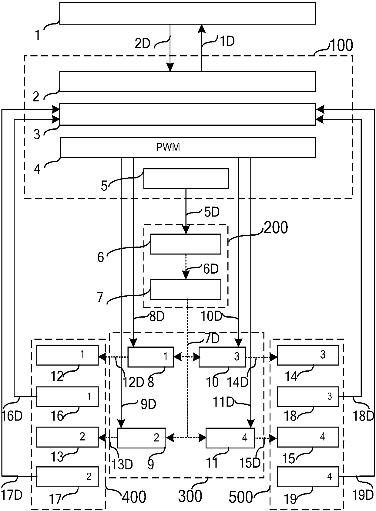
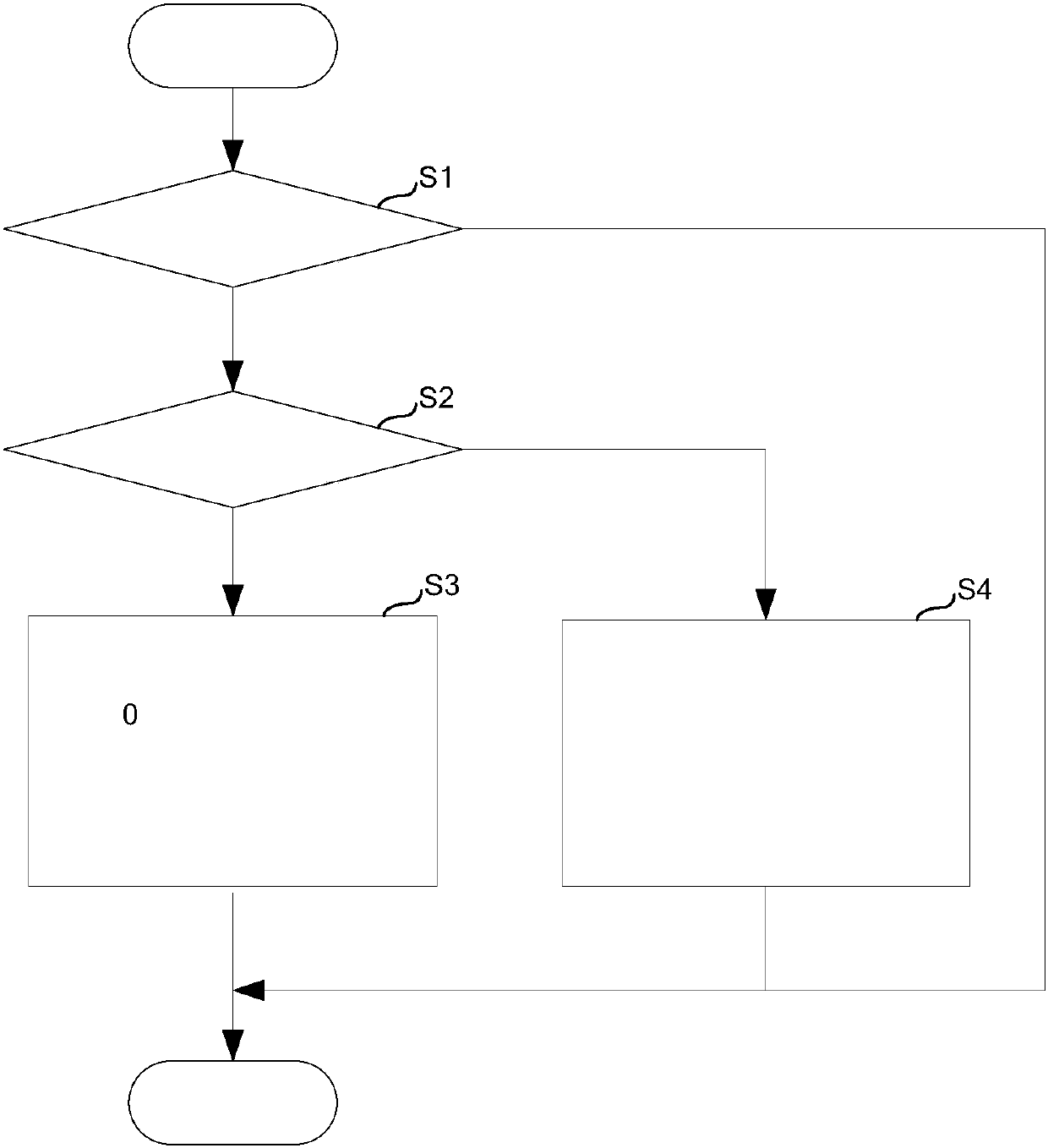
[0032] figure 2An embodiment of a method for antiskid control of a rail vehicle is shown. The electronic brake control unit 100 uniformly calculates the degree of wheel skidding, and reduces skidding by adjusting electric braking and air braking.
[0033] The electronic brake control unit 100 calculates the rotation speed and deceleration of each wheel according to the frequency signals 16D, 17D, 18D, and 19D of each wheel rotation sent by the bogie units 400, 500, and judges the speed of a certain wheel and the maximum speed among the four wheels. When the difference exceeds a certain threshold (such as 10-20km / h) or the deceleration of a certain wheel exceeds a certain threshold (such as 5-15km / h / s), it will be judged that the wheel is sliding (step S1, yes).
[0034] The electronic brake control unit judges that all wheels are not sliding (step S2, yes), and executes electric brake and air coordinated control (step S3): Figure 4 As shown, the electronic brake control un...
Embodiment approach 2
[0039] image 3 It represents another embodiment of the rail vehicle skid control method. The electronic brake control unit 100 uniformly calculates the degree of wheel skidding, and reduces skidding by adjusting electric braking and air braking.
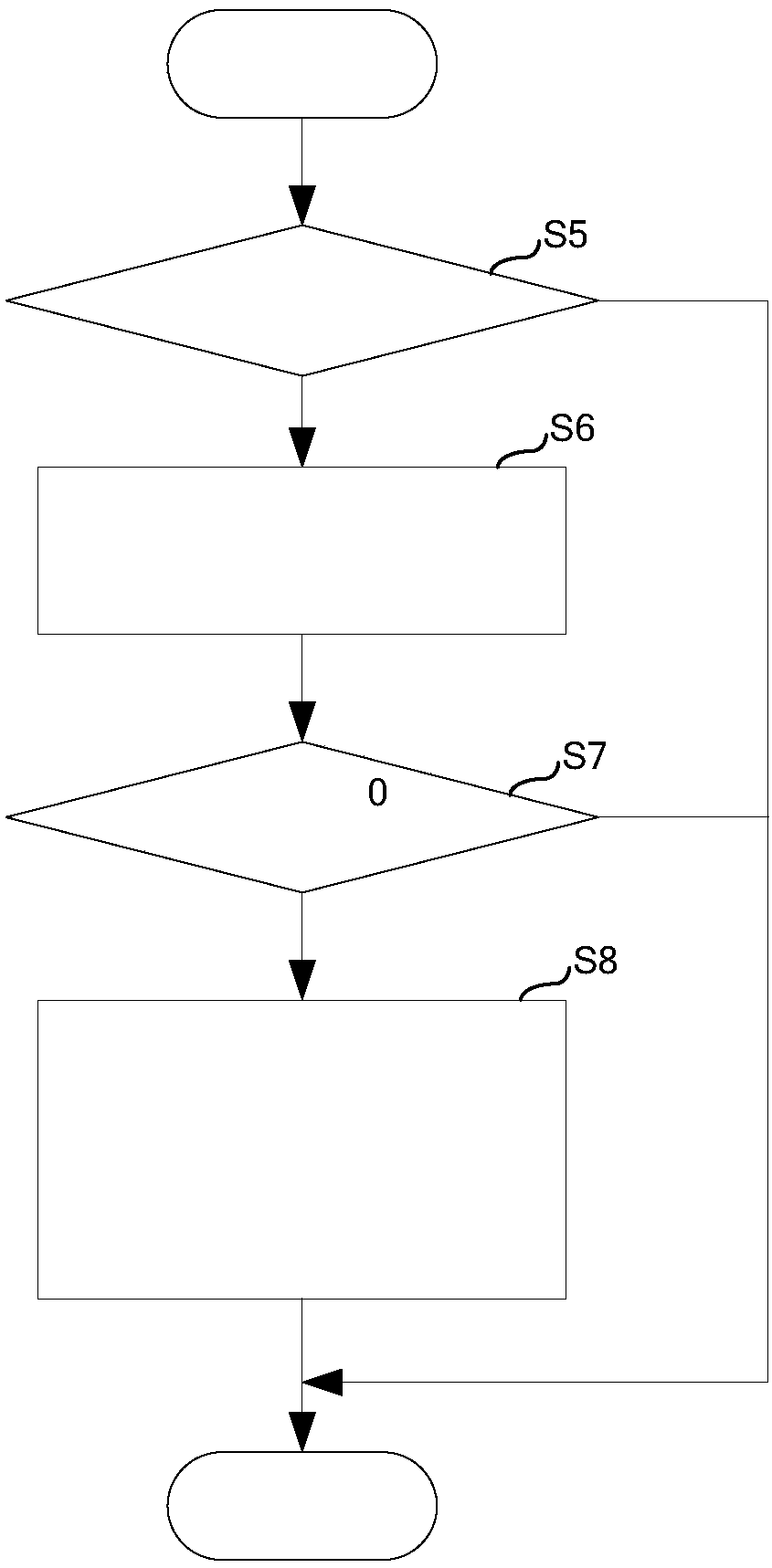
[0040] The electronic brake control unit 100 calculates the rotation speed and deceleration of each wheel according to the frequency signals 16D, 17D, 18D, and 19D of each wheel rotation sent by the bogie units 400, 500, and judges the speed of a certain wheel and the maximum speed among the four wheels. When the difference exceeds a certain threshold or the deceleration of a certain wheel exceeds a certain threshold, it will be judged that the wheel is slipping (step S5, Yes).
[0041] The electronic brake control unit 100 preferentially executes the electric brake control (step S6): if Figure 4 As shown, the electric braking control unit 100 reduces the corresponding electric braking according to the sliding amount, and sends a...
PUM
 Abstract
Description
Claims
Application Information