
Tank filling device with a vent for a liquid container

A filling device, liquid container technology, applied in the directions of liquid distribution, transportation or transfer device, distribution device, special distribution device, etc., can solve problems such as unreliable assurance

Active Publication Date: 2018-02-13
ANDREAS STIHL AG & CO KG
View PDF5 Cites 2 Cited by
  • Summary
  • Abstract
  • Description
  • Claims
  • Application Information

AI Technical Summary

Problems solved by technology

A uniform, undisturbed flow of liquid through the tank filling device is not reliably ensured for liquid-filled air channels

Method used


Image

  • Tank filling device with a vent for a liquid container
  • Tank filling device with a vent for a liquid container
  • Tank filling device with a vent for a liquid container

Examples


Embodiment Construction

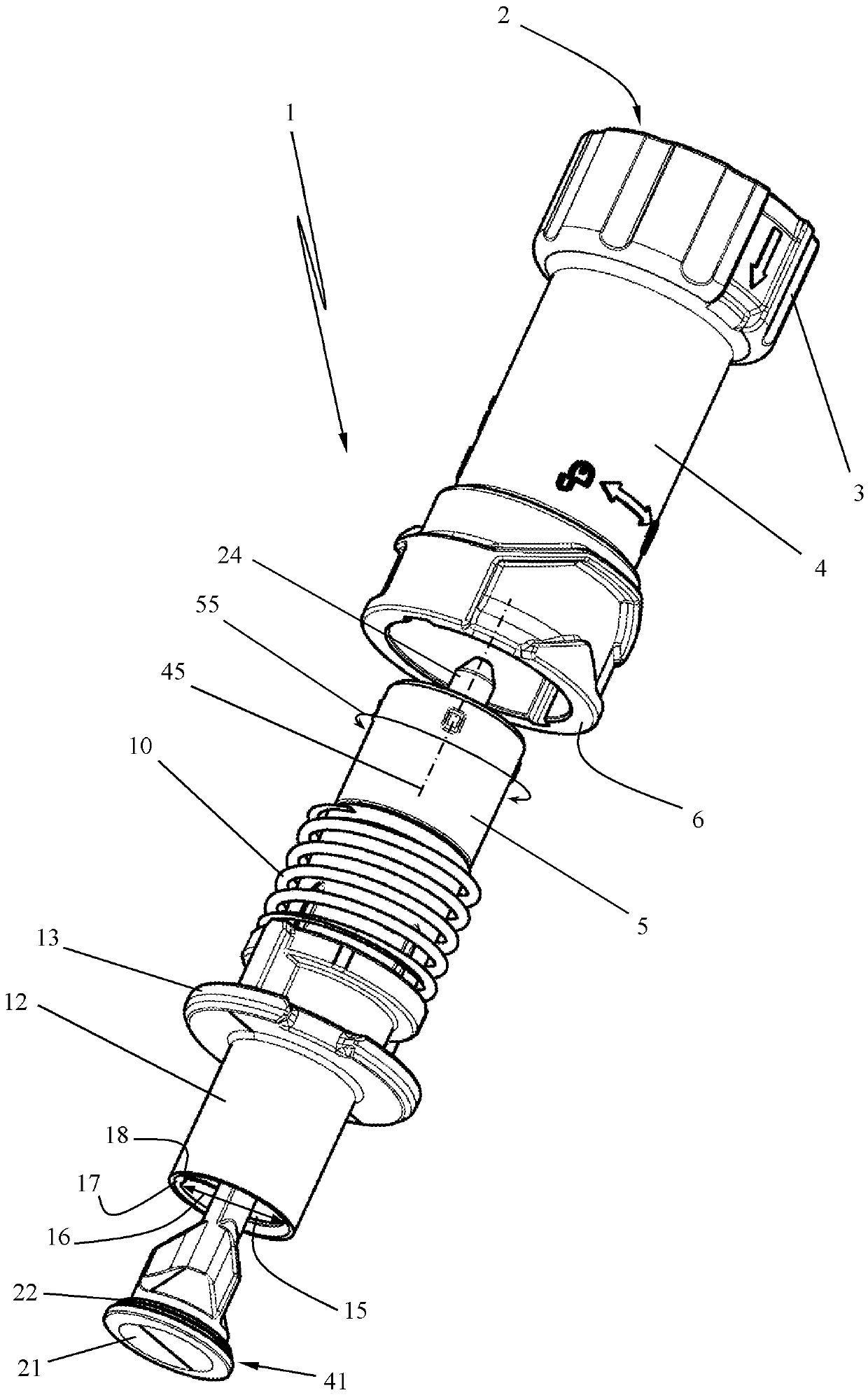
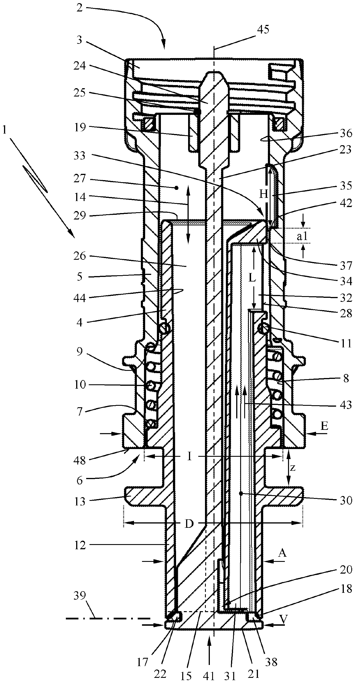
[0027] The storage tank filling device 1 presented in the exemplary embodiment has a mounting end 2 in the form of a screw cap 3 . The cylindrical storage tank filling device 1 is fixed on the liquid container 40 ( image 3 ) place. The liquid container 40 is, for example, a fuel container, which is carried by the user on the spot in order to resupply a working machine operated as an internal combustion engine.

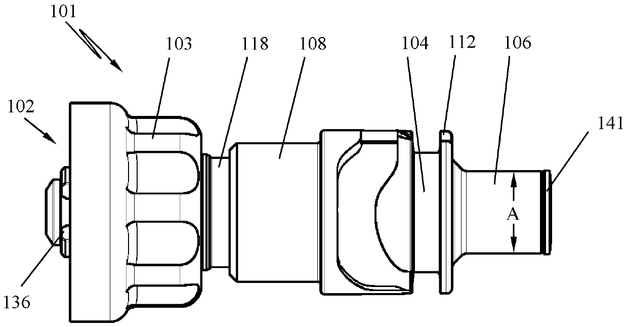
[0028] Such as figure 1 and 2 As shown, the tank filling device 1 essentially consists of a base body 4 with a mounting end 2 . The advantageously cylindrical base body 4 accommodates a suitably cylindrical actuating section 5 which is pushed into an end 6 of the base body 4 lying opposite the mounting end 2 . The actuating section 5 has an annular shoulder 7 which sinks into a widened section 8 of the open end 6 . The widened section 8 has an inner annular shoulder 9 . A spring 10 acts between the annular shoulder 9 of the widened section 8 and the annular shou...


PUM


Abstract

The invention relates to a tank filling device (1) for a liquid container (40). The tank filling device (1) has a base body (4) with mounting end (2) to secure the base body on a liquid container (40), and an actuating section (5) which is slidable lengthwise relative to the base body (4). A liquid valve (20) is connected to an outlet opening (15) for liquid and controls the outlet opening by being coupled to the actuating section (5) such that the liquid valve (15) is manually opened or closed by moving the actuating section. An air channel (30) with air inlet (31) and air outlet (32) supplies air into the liquid container (40) for pressure compensation. The air channel (30) extends from the liquid valve (20) toward the mounting end (2) and has an air valve (33) at the air outlet (32). For ensuring no-disturbance air supplying, the air outlet (32) of the air channel (30) is set to guide the actuating section (5) in the base body (4) and is composed of the actuating section (5) and thebase body (4). Hereon the air valve (20) is designed to a slot control valve between the actuatign section (5) and the base body (4).

Description

technical field [0001] The invention relates to a tank filling device for a liquid container, comprising a base body with a mounting end for fixing at the liquid container and with a longitudinally displaceable A guided actuation section with an outlet opening for the outflowing fluid, which is controlled by a fluid valve to be actuated manually. The fluid valve is coupled to the actuating section in such a way that the fluid valve can be opened and closed manually by displacing the actuating section. Furthermore, an air channel with an air inlet and an air outlet is provided for supplying air into the liquid container for pressure equalization in the liquid container, wherein the air channel runs from the area of ​​the liquid valve in the direction of the mounting end It extends upward and is provided with an air valve at its air outlet. Background technique [0002] A known tank filling device is fastened to a liquid container with a mounting end and has an actuating sec...

Claims


Application Information

Patent Timeline
Patent Type & Authority Applications(China)
IPC IPC(8): B67D7/36
CPCB65D47/28B65D47/32B67D7/42B67D7/005B67D7/04B67D7/36
Inventor R.阿当S.约斯B.维希特勒K-M.乌尔J.兰克
Owner ANDREAS STIHL AG & CO KG
Learn More