Clutch with good heat dissipation effect

A technology of heat dissipation effect and clutch, applied in the field of clutch, can solve the problems affecting clutch stability, friction disc wear, friction disc burning, etc., to reduce the risk of burning, work efficiently and stably, and prolong the working life.

Inactive Publication Date: 2018-02-13
WUHU HEFENG CLUTCH
View PDF6 Cites 2 Cited by
  • Summary
  • Abstract
  • Description
  • Claims
  • Application Information

AI Technical Summary

Problems solved by technology

[0002] During the working process of the clutch, since the friction disc will frequently contact and disconnect with the flywheel and the pressure plate, this process will generate a lot of heat. If the heat cannot be discharged from the clutch housing in time, it will not only affect the stability of the clutch when it is working, At the same time, it may also cause the friction disc to burn out, which will lead to the failure of the clutch; in addition, the friction disc of the clutch will continue to wear and tear, resulting in a lot of wear debris, which must be discharged out of the shell in time, otherwise it will affect the performance of the clutch, and eventually even lead to clutch damage

Method used


Image

  • Clutch with good heat dissipation effect
  • Clutch with good heat dissipation effect
  • Clutch with good heat dissipation effect

Examples


Embodiment 1

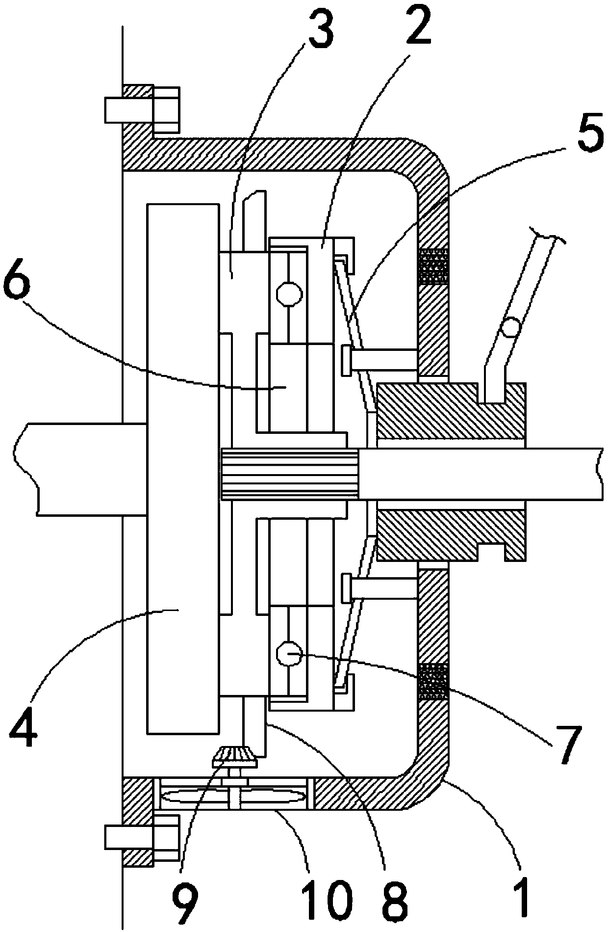
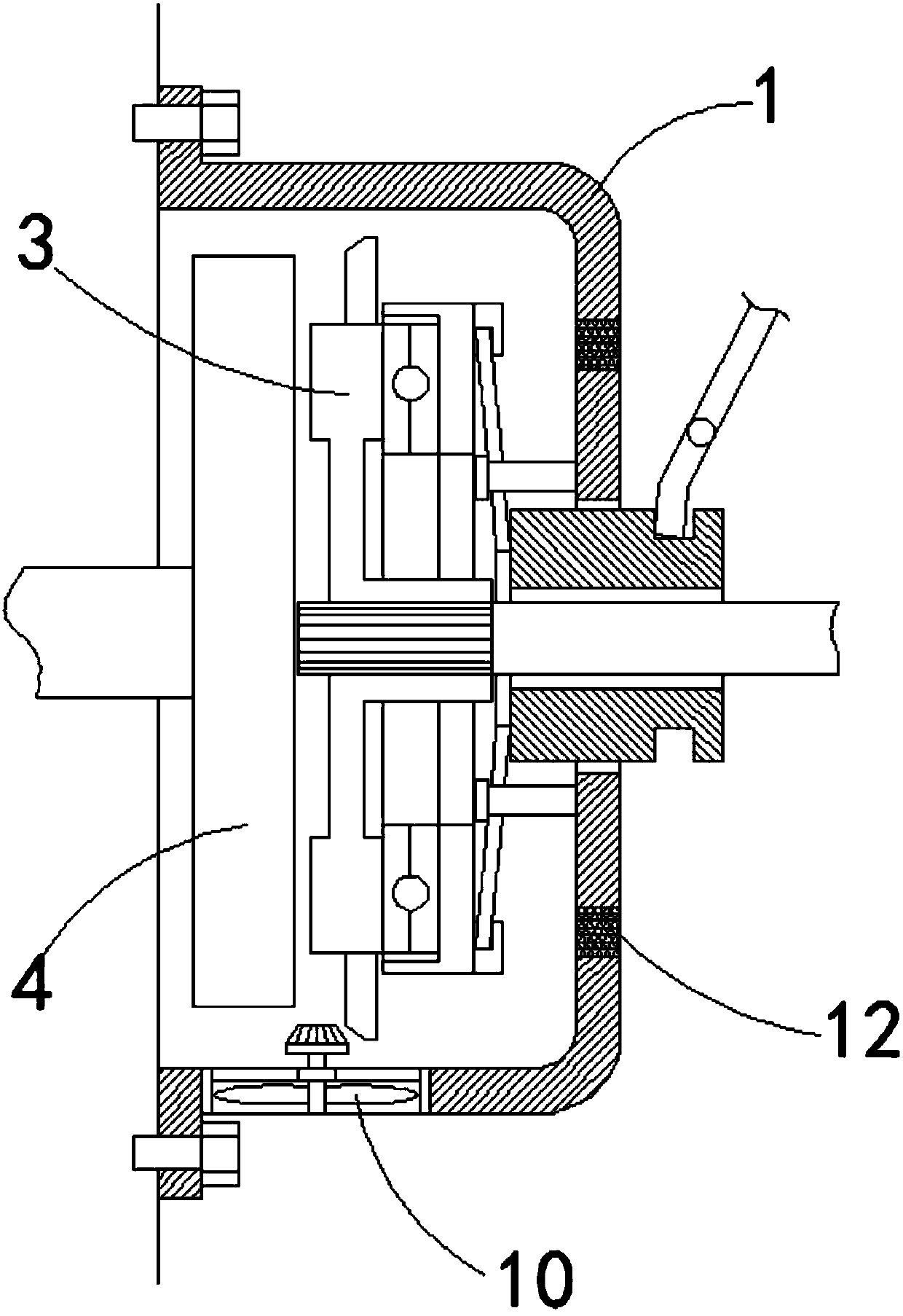
[0018] refer to Figure 1-2 The impeller shaft of the axial flow fan 10 extends to the inside of the casing 1, and a helical gear 9 is fixedly connected to the upper end of the impeller shaft. The helical gear 9 is located on the side of the ring 8 away from the pressure plate 2. One edge is provided with a first chamfer, and the first chamfer is evenly distributed with tooth grooves matching the helical gear 9. When the clutch is released, the helical gear 9 meshes with the tooth grooves, and the flywheel 4 drives the friction plate 3 to rotate. Then drive the axial flow fan 10 to rotate, and the heat generated by friction is quickly discharged. When the clutch is in the depressed state, the helical gear 9 is separated from the tooth groove, and the axial flow fan 10 stops rotating. The air outlet is discharged; the ring member 8 is connected with the axial flow fan 10 through gear transmission, which can avoid the problems of slipping and frictional loss.

Embodiment 2

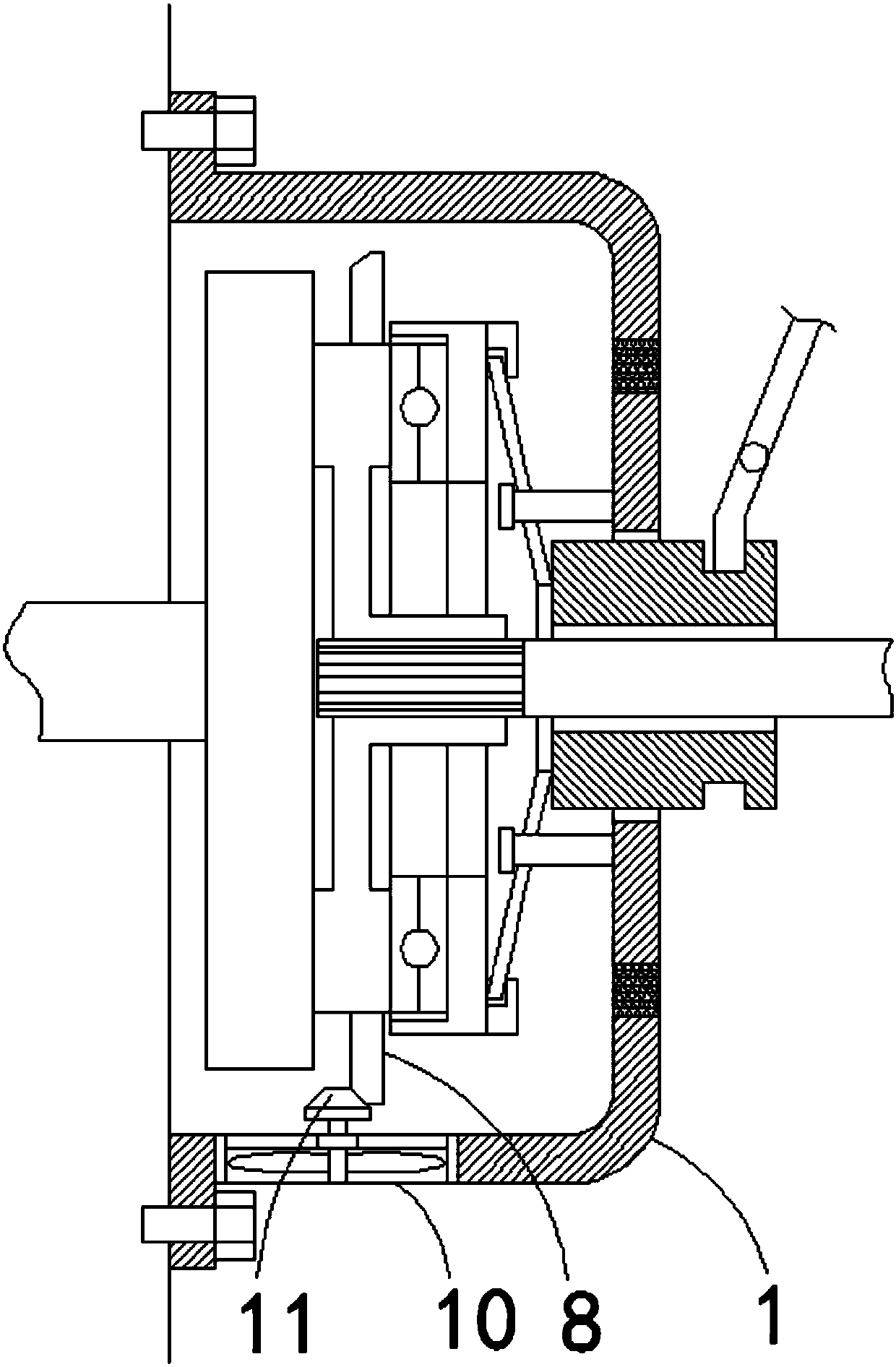
[0020] refer to image 3 The impeller shaft of the axial flow fan 10 extends to the inside of the casing 1, and a friction wheel 11 is fixedly connected to the upper end of the impeller shaft. One side edge is provided with a third chamfer. When the clutch is released, the helical gear 9 meshes with the tooth groove, and the flywheel 4 drives the friction plate 3 to rotate, which in turn drives the axial flow fan 10 to quickly discharge the heat generated by friction. When the clutch is in the depressed state, the helical gear 9 is disengaged from the tooth groove, the axial flow fan 10 stops rotating, and the wear debris generated when the friction plate 3 is working is discharged from the air outlet; the friction transmission method can avoid the sudden rotation of the friction plate 3 As a result, the toothing phenomenon occurs, which in turn affects the life of the friction wheel 3 .

[0021] In the present invention, a groove 6 is provided on the pressure plate 2, a thru...


PUM


Abstract

The invention discloses a clutch with a good heat dissipation effect. The clutch comprises a shell and a clutch assembly arranged in the shell. The shell is fixedly mounted on an engine shell. The clutch assembly comprises pressing discs, friction pieces, a flywheel and a transmission mechanism. The friction pieces are arranged between the pressing discs and the flywheel, and grooves are formed inthe sides, close to the friction pieces, of the pressing discs. Thrust ball bearings are arranged inside the grooves, one ends of the thrust ball bearings are connected with the side walls of the grooves, and the other ends of the thrust ball bearings are connected with the friction pieces. Annular parts are fixedly connected to the outer ring walls of the friction pieces. An exhaust outlet is formed in the side wall of the bottom of the shell and internally provided with an axial flow fan, and the axial flow fan is in transmission connection with the annular parts. The calorific value of theclutch can be decreased, meanwhile, rapid heat dissipation can further be conducted, and the long-term and stable work of the clutch is guaranteed.

Description

technical field [0001] The invention relates to the technical field of clutches, in particular to a clutch with good heat dissipation effect. Background technique [0002] During the working process of the clutch, since the friction disc will frequently contact and disconnect with the flywheel and the pressure plate, this process will generate a lot of heat. If the heat cannot be discharged from the clutch housing in time, it will not only affect the stability of the clutch when it is working, At the same time, it may also cause the friction disc to burn out, which will lead to the failure of the clutch; in addition, the friction disc of the clutch will continue to wear and tear, resulting in a lot of wear debris, which must be discharged out of the shell in time, otherwise it will affect the performance of the clutch, and eventually even lead to The clutch is damaged. For this reason, we propose a clutch with good heat dissipation effect to solve the above problems. Cont...

Claims


Application Information

Patent Timeline
Patent Type & Authority Applications(China)
IPC IPC(8): F16D13/72F16D13/68
CPCF16D13/72F16D13/68
Inventor 许道生
Owner WUHU HEFENG CLUTCH
Why Eureka
Try Eureka