Manual electric soldering bit capable of increasing welding efficiency of lead and bonding pad and improving welding reliability of lead and bonding pad

A technology for electric soldering iron tips and welding efficiency, which is applied in the direction of soldering irons, welding equipment, manufacturing tools, etc., can solve the problems of microstructural differences inside the weld, prolong the preheating and welding time, and reduce the reliability of solder joints, etc., to achieve shortening The effect of shortening welding time and preheating time and reducing the risk of burnout

Inactive Publication Date: 2013-02-20
HARBIN INST OF TECH
View PDF6 Cites 2 Cited by
  • Summary
  • Abstract
  • Description
  • Claims
  • Application Information

AI Technical Summary

Problems solved by technology

[0004] The present invention aims to solve the problem that the existing electric soldering iron heats the wire and the welding pad through heat conduction, which will prolong the preheating and welding time and cause the circuit board to be damaged by high temperature, and the uneven temperature of the part to be welded will cause the microstructure inside the weld There are differences, the long-term reaction makes the interface react violently and leads to the problem that the reliability of the solder joint is reduced, and a manual electric soldering iron tip that can improve the welding efficiency and reliability of the wire and the pad is provided.

Method used


Image

  • Manual electric soldering bit capable of increasing welding efficiency of lead and bonding pad and improving welding reliability of lead and bonding pad
  • Manual electric soldering bit capable of increasing welding efficiency of lead and bonding pad and improving welding reliability of lead and bonding pad

Examples


specific Embodiment approach 1

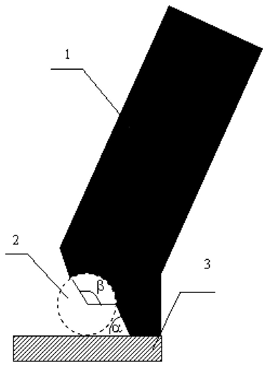
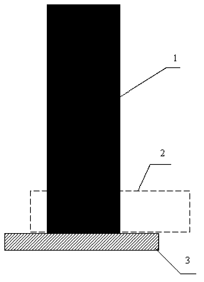
[0013] Embodiment 1: There is a gap in the middle of the tip end of the electric soldering iron, and the right part of the gap is longer than the left part of the gap.

[0014] The present invention includes the following advantages:

[0015] 1. Due to the design of the heat transfer structure of the electric soldering iron head, the heat transfer efficiency of the electric soldering iron, the wire and the pad can be improved, the preheating time before welding is shortened, and the risk of the circuit board being burned is reduced;

[0016] 2. The structure of the soldering iron head can ensure that the wire and pad quickly rise to the temperature to be soldered, and the temperature is uniform throughout the length of the wire and pad to be soldered. Therefore, in the process of adding welding wire to manual welding, the solder will quickly wet and spread on the surface of the wire to be welded and the metal surface of the pad, which will effectively shorten the welding time;...

specific Embodiment approach 2

[0020] Specific Embodiment 2: This embodiment differs from Specific Embodiment 1 in that: the shape of the notch is arc-shaped, triangular or square. Other structures and connections are the same as in the first embodiment.

specific Embodiment approach 3

[0021] Embodiment 3: This embodiment is different from Embodiment 1 in that: the bottom of the right part of the notch is a flat bottom, a pointed bottom or an arc-shaped bottom. Other structures and connections are the same as in the first embodiment.


PUM


Abstract

The invention discloses a manual electric soldering bit capable of increasing the welding efficiency of a lead and a bonding pad and improving the welding reliability of the lead and the bonding pad, which relates to a manual electric soldering bit and aims to solve the problem that a circuit board is damaged at high temperature because the preheating and welding time is prolonged by using the traditional electric soldering bit to heat the lead and the bonding pad in a thermal conduction way and the problem of welding point reliability reduction caused by long-time severe interface reaction because of differences of microstructures inside a welding line, which is caused by non-uniform temperature of a part to be welded. The manual electric soldering bit disclosed by the invention has a structure as follows: the middle part of the end of the electric soldering bit is provided with an opening with the length of 3-10mm; the right part of the opening is longer than the left part of the opening; and a welding wire is added in a space formed between the left part of the opening and the plane of the bonding pad in a welding process. The manual electric soldering bit is suitable for the field of welding engineering of electronic devices.

Description

technical field [0001] The invention relates to a manual electric soldering iron tip. Background technique [0002] Manual brazing is a commonly used brazing method, which is widely used in the field of electronic product manufacturing. During the brazing process, the solder will melt under the action of the heat carried by the electric soldering iron, and at the same time wet and spread on the surface of the material to be welded heated by the electric soldering iron. After the soldering iron is removed, the solder will cool and solidify to form a manual solder joint. When the soldering iron preheats the materials to be soldered and during the soldering process, if the heating time is too long, it may cause the burning of the circuit board and other materials that are not resistant to high temperature. In addition, the reliability of the solder joint is determined by the wetting and spreading of the solder on the surface of the metal to be welded and its internal microstru...

Claims


Application Information

Patent Timeline
Patent Type & Authority Applications(China)
IPC IPC(8): B23K3/03
Inventor 刘威王春青田艳红安荣杭春进
Owner HARBIN INST OF TECH
Why Eureka
Try Eureka