A hydraulic rotary joint mechanical transmission clutch

A technology of mechanical transmission and hydraulic rotation, which is applied in the field of clutches, can solve the problems of inconvenient replacement and easy damage of rotary joints, and achieve the effects of convenient replacement, less force displacement, and increased service life

Active Publication Date: 2019-07-02
WUHU HEFENG CLUTCH
View PDF12 Cites 0 Cited by
  • Summary
  • Abstract
  • Description
  • Claims
  • Application Information

AI Technical Summary

Problems solved by technology

[0003] The purpose of the present invention is to solve the problem that the rotary joint in the prior art is easily damaged and inconvenient to replace, and proposes a hydraulic rotary joint mechanical transmission clutch

Method used


Image

  • A hydraulic rotary joint mechanical transmission clutch
  • A hydraulic rotary joint mechanical transmission clutch
  • A hydraulic rotary joint mechanical transmission clutch

Examples


Embodiment Construction

[0015] The following will clearly and completely describe the technical solutions in the embodiments of the present invention with reference to the accompanying drawings in the embodiments of the present invention. Obviously, the described embodiments are only some, not all, embodiments of the present invention.

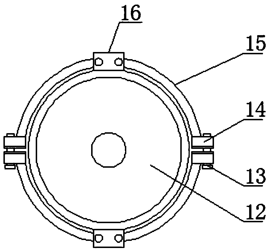
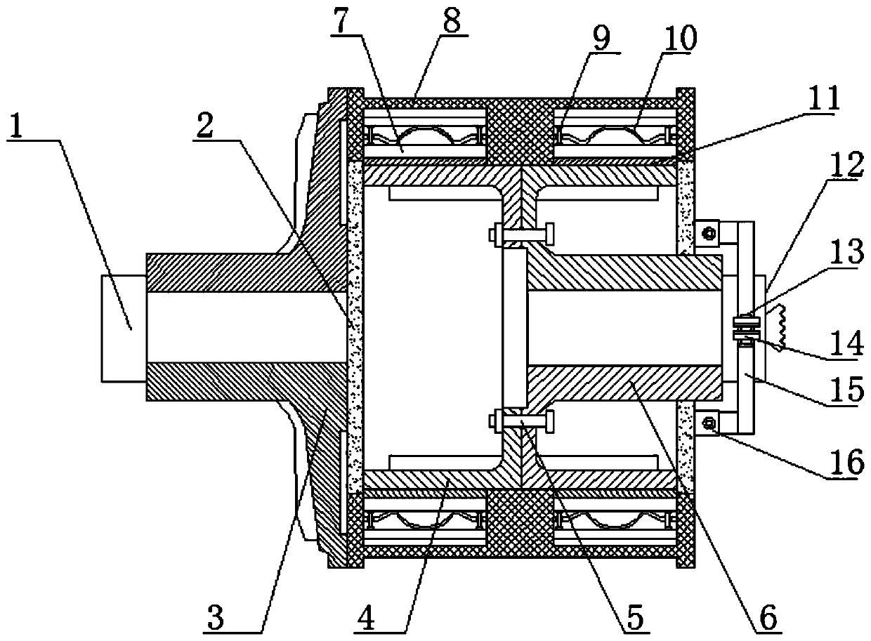
[0016] refer to Figure 1-2 , a hydraulic rotary joint mechanical transmission clutch, including a housing 8, the housing 8 is provided with a cavity, the cavity is symmetrically provided with two first side plates 2, and the two first side plates 2 are provided with There is a second side plate 4 and a driven wheel 6, and a fixing device 5 is arranged between the driven wheel 6 and the second side plate 4, so that the position between the driven wheel 6 and the second side plate 4 is fixed, and the second side plate 4 and the second side plate 4 are fixed. A return spring 10, a torque plate 7 and a rubber sheet 11 are sequentially arranged between the housing 8 and ...


PUM


Abstract

The invention discloses a mechanical transmission clutch of a hydraulic rotary joint. The mechanical transmission clutch comprises a shell, the shell is internally provided with a cavity, and two first side plates are symmetrically arranged in the cavity; a second side plate and a driven wheel are arranged between the two first side plates, and a fixing device is arranged between the driven wheeland the second side plate; a reset spring, a torque plate and a rubber sheet are sequentially arranged between the second side plate and the shell as well as between the driven wheel and the shell; sliding rods are arranged at the two ends of the reset spring, and both the two ends of the sliding rods penetrate through the reset spring to be rotatably connected with the shell and the torque platecorrespondingly; and a star wheel is arranged on one side of the shell, a first hollow groove is formed in the star wheel, and a driving shaft is arranged in the first hollow groove. The mechanical transmission clutch of the hydraulic rotary joint is not easy to displace by force, so that the rotary joint is effectively protected, replacing of the rotary joint is convenient, and the service life of the clutch is prolonged.

Description

technical field [0001] The invention relates to the technical field of clutches, in particular to a hydraulic rotary joint mechanical transmission clutch. Background technique [0002] Pneumatic clutch is a commonly used mechanism in existing machinery, and can be divided into piston type, diaphragm type and pneumatic tire type according to the cylinder structure. The bearing power output structure of the existing pneumatic clutch is relatively simple. Generally, pulleys and flanges are directly used. The contact mode between the flange and the power input shaft also adopts a simple deep groove ball bearing structure, and adopts a rotary Joints, during use, due to the operation at high speeds, the axial force of the bearing structure will cause the rotary joint to shift, and the axial force generated during operation is likely to generate high temperature, resulting in damage to the rotary joint, inconvenient replacement, and shortened clutch life. service life. Contents ...

Claims


Application Information

Patent Timeline
Patent Type & Authority Patents(China)
IPC IPC(8): F16D25/12
CPCF16D25/12
Inventor 许道生
Owner WUHU HEFENG CLUTCH
Why Eureka
Try Eureka