Eureka AIR delivers breakthrough ideas for toughest innovation challenges, trusted by R&D personnel around the world.

Automatic wire plugging structure of flat-wire motor stator

A motor stator, automatic technology, applied in the direction of electric components, manufacturing motor generators, electrical components, etc., can solve the problems of reducing the motor slot full rate, low production efficiency, low motor slot full rate, etc., to improve insulation reliability, Improve productivity, eliminate the effect of using

Pending Publication Date: 2018-02-13
HEFEI JUYI POWER SYST CO LTD
View PDF0 Cites 5 Cited by
  • Summary
  • Abstract
  • Description
  • Claims
  • Application Information

AI Technical Summary

Problems solved by technology

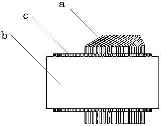
In the prior art, the stator wire insertion method of the flat wire motor is generally that a single coil a is inserted into the stator slot of the stator core b one by one, such as figure 2 As shown, the coil inserted later is easy to scratch the coil that has been inserted. In order to ensure the insulation reliability between the enameled flat wires, each wire should be separated by insulating paper c
This insertion method is not easy to automate, and the production efficiency is low
Too much insulating paper in the slot will reduce the slot fullness of the motor. The more wires in the slot, the lower the slot fullness of the motor. It is difficult to reflect the advantages of high stator slot fullness of the flat wire motor, and to a certain extent restricts the winding wire Dimensional Design Flexibility

Method used


Image

  • Automatic wire plugging structure of flat-wire motor stator
  • Automatic wire plugging structure of flat-wire motor stator
  • Automatic wire plugging structure of flat-wire motor stator

Examples


Embodiment Construction

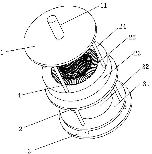
[0022] Such as image 3 and 4 As shown, the flat wire motor stator automatic wire insertion structure disclosed by the present invention includes four vertical guide posts 4 and a first support base 1 and a second support base 2 mechanically fixed on the guide posts in turn from top to bottom. and the third support base 3; the guide post above the third support base 3 is provided with a sliding base 31 carrying a stator core 32, and the sliding base 31 can move up and down along the guide post; the second support base 2 A ring-shaped slide pin guide rail 21 is fixed on the slide pin guide rail 21. A number of slide pins 22 that can slide radially on the slide pin guide rail are placed on the slide pin guide rail. A gap for placing the winding coil 24 is formed between adjacent slide pins The opening wire slot; the outer side of the sliding pin 22 is also nested with a sliding extrusion body 23 that can slide up and down along the guide post 4, acting on the sliding pin 22 to ...


PUM


Abstract

The invention discloses an automatic wire plugging structure of a flat-wire motor stator. The automatic wire plugging structure comprises a vertical guide pillar and three support bases sequentially fixed onto the guide pillar from top to bottom, and a slide base bearing a stator core is arranged above the third support base; a slide pin guide is fixed on the second support base, radial slide chutes evenly distributed in a ring are arranged in the upper end of the slide pin guide, and a slide pin capable of sliding radially along each slide chute is placed in the slide chute; a sliding extrusion body is embedded in the outer side of each slide pin; a press component is arranged on the first support base. The automatic wire plugging structure is ingenious in structure and simple and reliable, production efficiency can be improved, the possibility that enameled flat wires are scratched during the course that a winding coil is plugged in the stator core is reduced, insulation reliabilityamong the enameled flat wires is improved, and use of insulation paper among the enameled flat wires in the chutes is favorably avoided.

Description

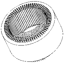
technical field [0001] The invention relates to a stator winding of an automobile drive motor or a generator, in particular to an automatic wire insertion structure for a flat wire motor stator. Background technique [0002] The winding of the flat wire motor is a square wire, and the winding coil is generally embedded in the stator slot by insertion, such as figure 1 Shown is a schematic view of the stator slots inside the stator core. In the prior art, the stator wire insertion method of the flat wire motor is generally that a single coil a is inserted into the stator slot of the stator core b one by one, such as figure 2 As shown, the coil inserted later is easy to scratch the coil that has been inserted. In order to ensure the insulation reliability between the enameled flat wires, each wire should be separated by insulating paper c. This wire insertion method is not easy to realize automation, and production efficiency is lower. Too much insulating paper in the slot...

Claims


Application Information

Patent Timeline
Patent Type & Authority Applications(China)
IPC IPC(8): H02K15/085
CPCH02K15/085
Inventor 刘蕾朱标龙田旭
Owner HEFEI JUYI POWER SYST CO LTD
Why Eureka
Eureka Blog
Learn More