Stainless steel pipe grinding device

A stainless steel pipe and equipment technology, which is applied in the field of stainless steel pipe grinding equipment, can solve problems such as elongation, stainless steel pipes are easy to scratch, and labor intensity is high, so as to achieve the effect of improving the service life

Active Publication Date: 2018-02-16
昆山赫斯顿精密五金机械有限公司
View PDF6 Cites 4 Cited by
  • Summary
  • Abstract
  • Description
  • Claims
  • Application Information

AI Technical Summary

Problems solved by technology

Since the stainless steel pipe is easy to scratch, the worker must wear a protective cover when grinding
At present, in the process of grinding stainless steel welds, most of the welds are polished manually, which not only has low efficiency, poor stability, and high labor intensity, but also the disc grinding head is easy to scratch the outer surface of the stainless steel pipe. , affecting the quality. In addition, the strength of the abrasive belt on the traditional mechanical grinding device when it touches the stainless steel pipe cannot be adjusted. It is easy to be stretched after long-term use, which will affect the tension effect of the abrasive belt. The structure is complex and difficult to maintain. Manufacturing The cost and maintenance cost are high, which cannot meet the needs of existing small and medium-sized enterprises

Method used


Image

  • Stainless steel pipe grinding device
  • Stainless steel pipe grinding device
  • Stainless steel pipe grinding device

Examples


Embodiment Construction

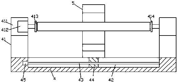
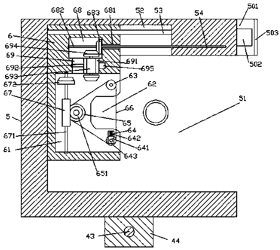
[0026] like Figure 1-Figure 6As shown, a kind of grinding equipment for stainless steel pipes of the present invention includes a base frame 4 and a grinding support frame 5 arranged on the base frame 4, and a receiving groove 51 is arranged in the front end surface of the grinding support frame 5, and the The rear side of the inner top wall of the accommodation groove 51 is provided with a first sliding groove 52 extending forward and backward, and the first sliding groove 52 is provided with a guide rod 53 extending forward and backward, and the inner wall of the front side of the first sliding groove 52 is provided with The threaded hole 54 extended on the front side, the grinding mechanism 6 extending downward is connected to the guide rod 53 by sliding fit, the bottom extension section of the grinding mechanism 6 extends into the accommodation groove 51, and the accommodation groove 51 A grinding groove 61 is provided in the front end surface of the grinding mechanism 6 ...


PUM


Abstract

The invention discloses a stainless steel pipe grinding device. The stainless steel pipe grinding device comprises a base frame and a grinding supporting frame arranged on the base frame; a containinggroove is formed in the front side end face of the grinding supporting frame, a first sliding groove extending front and back is formed in the rear side of the inner top wall of the containing groove, a guide rod which extends front and back is arranged in the first sliding groove, a thread hole extending towards the front side is arranged on the inner wall of the front side of the first slidinggroove, a grinding mechanism which extends downwards is in sliding fit connection to the guide rod, and the bottom extension segment of the grinding mechanism extends into the containing groove. The stainless steel pipe grinding device is simple in structure, reasonable in design, low in manufacturing cost and maintaining cost and capable of automatically controlling grinding transmission switching and grinding mechanism moving control, the grinding supporting frame can move left and right for work, the grinding needs of a stainless steel pipe at the different welding line positions can be met, in addition, a rotating motor drives a stainless steel pipe to achieve comprehensive welding line grinding, and meanwhile, grinding efficiency is improved.

Description

technical field [0001] The invention relates to the technical field of steel pipe processing, in particular to a grinding equipment for stainless steel pipes. Background technique [0002] In the splicing process of stainless steel pipes, it is often necessary to grind the weld seam. Since the stainless steel pipe is easy to scratch, the worker must wear a protective cover when grinding. At present, in the process of grinding stainless steel welds, most of the welds are polished manually, which not only has low efficiency, poor stability, and high labor intensity, but also the disc grinding head is easy to scratch the outer surface of the stainless steel pipe. , affecting the quality. In addition, the strength of the abrasive belt on the traditional mechanical grinding device when it touches the stainless steel pipe cannot be adjusted. It is easy to be stretched after long-term use, which will affect the tension effect of the abrasive belt. The structure is complex and diff...

Claims


Application Information

Patent Timeline
Patent Type & Authority Applications(China)
IPC IPC(8): B24B21/00B24B21/20B24B21/18B24B41/06
CPCB24B21/00B24B21/18B24B21/20B24B41/06
Inventor 郑杰陈剑波
Owner 昆山赫斯顿精密五金机械有限公司
Why Eureka
Try Eureka