
Wire harness used for integrated wallboard, injection molding device and production method

A technology that integrates wall panels and production methods, applied in the manufacture of wire harnesses, conductors, insulated cables, etc., can solve the problems of dust, impact, and speed up the progress of the construction period

Inactive Publication Date: 2018-02-16
WUHU INST OF TECH
View PDF5 Cites 3 Cited by
  • Summary
  • Abstract
  • Description
  • Claims
  • Application Information

AI Technical Summary

Problems solved by technology

[0002] During the home improvement process, most owners will rewire the wiring harness laid by the developer to meet their own needs. The traditional wiring method is to slot and drill holes on the wall, and pass the wire through the PVC through the pre-embedded PVC conduit. The wire pipe is passed through to complete the layout. Using this method will not only generate a lot of dust during the slotting process, but also affect the construction period
[0003] At present, more and more owners use integrated wall panels in decoration. On the one hand, it can avoid painting the wall panels. On the other hand, the styles of integrated wall panels are also rich and varied, which can meet the needs of owners to a greater extent Requirements, since the integrated wallboard itself has a thickness of about 1cm, if the traditional slotted wiring method is still used in the wiring process, it will inevitably cause a lot of limitations and inconveniences. In order to avoid opening on the wall when using the integrated wallboard Groove wiring, then a wire harness for integrated wall panels is required that can be directly arranged on the integrated wall panels to reduce labor intensity and speed up the schedule

Method used


Image

  • Wire harness used for integrated wallboard, injection molding device and production method
  • Wire harness used for integrated wallboard, injection molding device and production method
  • Wire harness used for integrated wallboard, injection molding device and production method

Examples


Embodiment Construction

[0030] Specific embodiments of the present invention will be described in detail below in conjunction with the accompanying drawings. It should be understood that the specific embodiments described here are only used to illustrate and explain the present invention, and are not intended to limit the present invention.

[0031] In the present invention, unless otherwise specified, the orientation words included in the term such as "up, down, left, right, front, back, inside and outside" only represent the orientation of the term in the normal use state, or the common name understood by those skilled in the art. , and should not be construed as a limitation of this term.

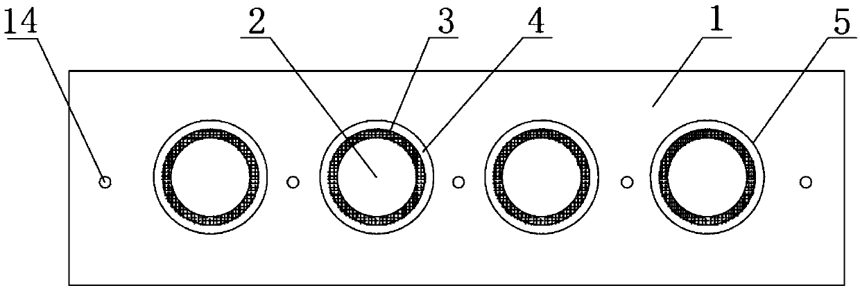
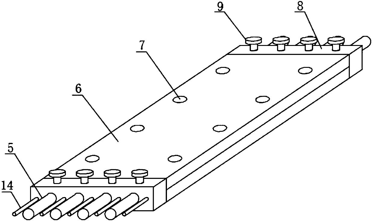
[0032] see figure 1 with 3 The shown wire harness for integrated wallboards, the wire harness includes: a wire core 5 and an outer cladding 1, the longitudinal section of the outer cladding 1 along its width direction is square, and multiple strands of the wire core 5 are formed along the outer cladding. 1 a...


PUM

PropertyMeasurementUnit
Thicknessaaaaaaaaaa
Diameteraaaaaaaaaa

Abstract

The invention discloses a wire harness used for an integrated wallboard, an injection molding device and a production method. The longitudinal section of a wire harness outer cladding layer is square,and a plurality of wire cores are arranged inside the outer cladding layer in the width direction of the outer cladding layer; in the injection molding device used for production of the wire harness,an injection molding cavity is formed in a mold, and the two ends of the mold are connected into two clamping mechanisms in an inserted mode and are clamped; injection molding holes are formed in themold, and an injection molding pump communicates with a storage and the injection molding cavity; the two ends of the mold are coaxially provided with first left limiting holes and first right limiting holes communicating with the injection molding cavity, and the multiple first left limiting holes and the multiple first right limiting holes are formed in the width direction of the mold; and a plurality of wire core clamping holes which are coaxial with the first left limiting holes or the first right limiting holes are formed in the clamping mechanisms, and the method for producing the wireharness through the injection molding device comprises the steps of cutting, positioning, pouring and finishing. The wire harness produced through the production method by using the injection moldingdevice is specially used in the integrated wallboard.

Description

technical field [0001] The invention relates to indoor wires, in particular to a wire harness for an integrated wallboard, an injection molding device and a production method. Background technique [0002] During the home improvement process, most owners will rewire the wiring harness laid by the developer to meet their own needs. The traditional wiring method is to slot and drill holes on the wall, and pass the wire through the PVC through the pre-embedded PVC conduit. The wire pipe is passed through to complete the layout. Using this method will not only generate a lot of dust during the slotting process, but also affect the construction period. [0003] At present, more and more owners use integrated wall panels in decoration. On the one hand, it can avoid painting the wall panels. On the other hand, the styles of integrated wall panels are also rich and varied, which can meet the needs of owners to a greater extent Requirements, since the integrated wallboard itself has...

Claims


Application Information

Patent Timeline
IPC IPC(8): B29C45/14B29C45/17B29C33/12H01B7/00H01B13/012
CPCB29C45/14065B29C45/14221B29C2045/14229H01B7/0045H01B13/01209H01B13/01236H01B13/01254H01B13/01263
Inventor 浦强松杨文
Owner WUHU INST OF TECH
Learn More