Method for measuring relative positions of propeller and rudder blades of vessel

A relative position and propeller technology, applied in ship components, ship construction, ship design, etc., can solve problems that cannot be directly measured

Active Publication Date: 2018-02-16
HUDONG ZHONGHUA SHIPBUILDINGGROUP
View PDF5 Cites 6 Cited by
  • Summary
  • Abstract
  • Description
  • Claims
  • Application Information

AI Technical Summary

Problems solved by technology

[0007] During ship construction, the above values ​​cannot be directly measured, and construction personnel need to conduct a series of related work in the early stage to ensure that the relative positions of the rudder and paddles meet the design and specification requirements after the completion of the installation work. difficulty

Method used


Image

  • Method for measuring relative positions of propeller and rudder blades of vessel
  • Method for measuring relative positions of propeller and rudder blades of vessel
  • Method for measuring relative positions of propeller and rudder blades of vessel

Examples


Embodiment Construction

[0032] In order to make the object, technical solution and advantages of the present invention clearer, the present invention is described below through specific embodiments shown in the accompanying drawings. It should be understood, however, that these descriptions are exemplary only and are not intended to limit the scope of the present invention. Also, in the following description, descriptions of well-known structures and techniques are omitted to avoid unnecessarily obscuring the concept of the present invention.

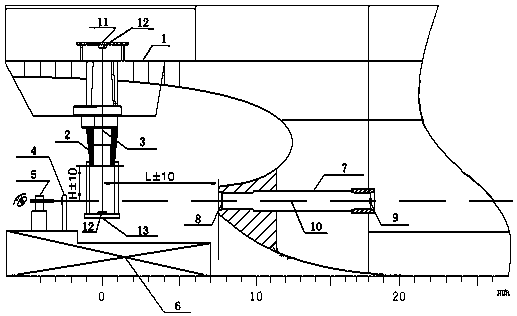
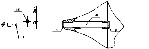
[0033] combine figure 1 , figure 2 This embodiment is described. The integrated suspension rudder of the present invention is applicable to the rudder system without boring processing, and is especially suitable for the propulsion system of a ship with a highly matched hydrodynamic performance of the propeller and the rudder. It should be noted that the determination and measurement of the relative positions of the ship's propeller and rudder blades is carr...


PUM


Abstract

The invention discloses a method for measuring relative positions of a propeller and rudder blades of a vessel. The method is used for an integrated hanging rudder which does not need boring and processing, of a rudder system, and specifically comprises the following steps of firstly, fixing an upper sliding assembly on a steering engine deck, fixing a lower sliding assembly on the lower end surface of a rudder stock cylinder, and adjusting the upper sliding assembly and the lower sliding assembly to enable a steel wire to be located in a central axis of the rudder stock cylinder, wherein thesteel wire can express a rudder system center line; and then finding out a target center of a head reference target and a target center of a tail reference target by a tacheometry, and finding out a straight line by a collimating telescope, wherein the straight line sequentially passes through the target center of the tail reference target and the target center of the head reference target, and isa shaft system center line. According to the method disclosed by the invention, the relative positions and the relative distance between the propeller and the rudder blades are measured by using therudder system center line and the shaft system center line as the references; a stern shaft pipe is bored and processed according to measurement data, so that the shaft system center line is solidified, and the situation that regulated requirements of the relative positions of the propeller and a rudder are met is guaranteed.

Description

technical field [0001] The invention relates to the technical field of ship building and processing, in particular to a method for measuring the relative positions of a ship propeller and a rudder blade. Background technique [0002] With the development of energy-saving and high-efficiency ships, ship designers are trying to optimize the streamline shape of the hull shell as much as possible, and at the same time, they are also working hard on the efficient matching of propeller and rudder power performance. At present, a large number of new ships have adopted an energy-saving and efficient propulsion system design. There are two main measures used, the use of high-efficiency flap rudders and optimized propeller rudder matching. [0003] The high-efficiency flap rudder adds follow-up flaps behind the main rudder, which greatly improves the operational performance of the rudder blades. At the same time, high-efficiency rudder balls are used. The use of rudder balls fills the...

Claims


Application Information

Patent Timeline
Patent Type & Authority Applications(China)
IPC IPC(8): B63B9/00
CPCB63B71/00
Inventor 黄中坚姚仁光瞿伟刚王辉
Owner HUDONG ZHONGHUA SHIPBUILDINGGROUP
Why Eureka
Try Eureka