A kind of unmanned aerial vehicle rotor folding structure and unmanned aerial vehicle

A technology of folding structure and aircraft rotor, which is applied in the direction of rotorcraft, unmanned aircraft, fuselage, etc., can solve the problems that the rotor cannot be folded, the rotor is easy to be damaged, and takes up a large space, so as to achieve compact structure, convenient folding, The effect of easy disassembly and assembly

Active Publication Date: 2020-11-06
四川金瑞穗科技有限公司
View PDF5 Cites 2 Cited by
  • Summary
  • Abstract
  • Description
  • Claims
  • Application Information

AI Technical Summary

Problems solved by technology

[0002] At present, there are various drones on the market, but none of these drones can fold the rotors, which is not only inconvenient to carry, but also easy to damage the rotors during transportation, and when the rotors are unfolded, they are larger and take up a lot of space , not easy to place

Method used


Image

  • A kind of unmanned aerial vehicle rotor folding structure and unmanned aerial vehicle
  • A kind of unmanned aerial vehicle rotor folding structure and unmanned aerial vehicle
  • A kind of unmanned aerial vehicle rotor folding structure and unmanned aerial vehicle

Examples


Embodiment approach 1

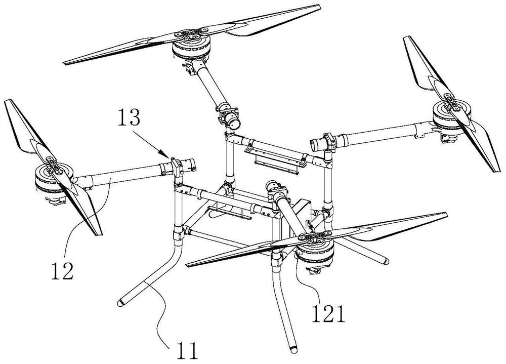
[0032] refer to Figure 1-4 As shown, the UAV rotor folding structure provided by Embodiment 1 of the present invention includes a frame 11 , a rotor assembly 12 and a folding assembly 13 .

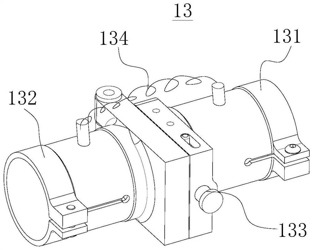
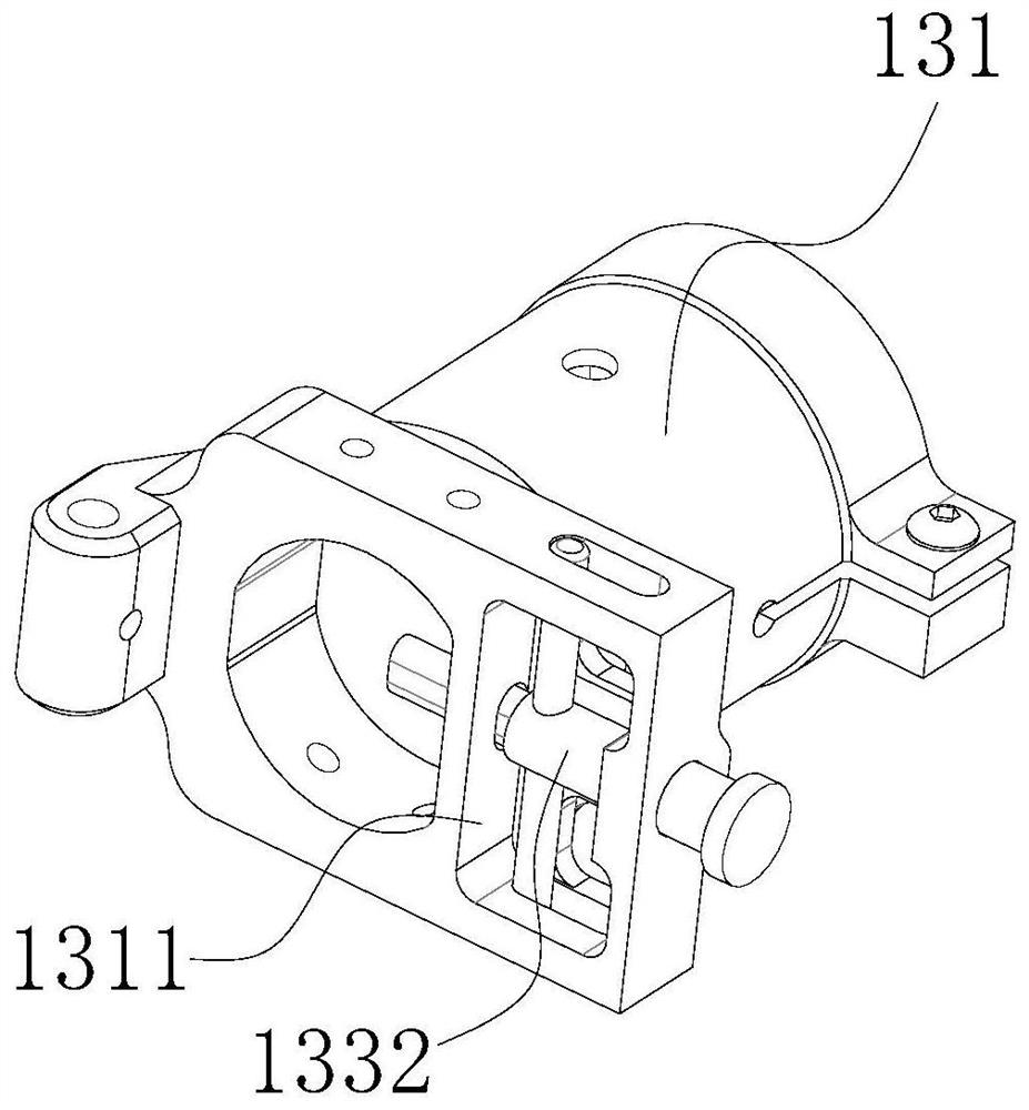
[0033] The folding assembly 13 includes a first adapter 131 and a second adapter 132 .

[0034] One end of the first adapter 131 is rotatably connected to one end of the second adapter 132 , and the first adapter 131 and the second adapter 132 may be connected by a pin or by a hinge.

[0035] A buckle 133 for keeping the first adapter 131 and the second adapter 132 relatively fixed may also be provided between the first adapter 131 and the second adapter 132; when the buckle 133 is locked, the first adapter 131 Keep relatively fixed with the second adapter 132; when the buckle 133 is opened, the first adapter 131 and the second adapter 132 can rotate relatively. The buckle 133 includes a lock hook 1331 and a lock core 1332, the lock hook 1331 is arranged on the second adapter 132, the f...

Embodiment approach 2

[0044] refer to Figure 5 As shown, a UAV provided by Embodiment 2 of the present invention includes a control system and a UAV rotor folding structure.

[0045] It should be noted that in this embodiment, the UAV rotor folding structure can adopt the UAV rotor folding structure in Embodiment 1, and its structure, working principle and technical effects can refer to the corresponding content in Embodiment 1. No detailed description is given here.

[0046] In this embodiment, the number of rotor assemblies 12 is four, and the four rotor assemblies 12 are respectively fixed at four corners of the upper end of the frame 11 through folding assemblies 13 .

[0047] It should be noted that the rotor assembly 12 can adopt the prior art, and the number of the rotor assembly 12 can also be more than four. In order to ensure the stability of the drone during flight, the number of the rotor assembly 12 should be an even number, and symmetrically set on both sides of the rack 11.

[00...


PUM


Abstract

The invention provides a UAV rotor folding structure and UAV, which belong to the field of UAV technology. The UAV rotor folding structure includes a frame, a rotor assembly and a folding assembly, and the rotor assembly is supported on the frame by the folding assembly. Above, the folding assembly includes a first adapter and a second adapter, the first adapter is fixed on the upper end of the frame, one end of the second adapter is connected to one end of the rotor assembly, and the end of the second adapter is far away from the rotor assembly. One end of the first adapter is rotatably connected, and there is also a buckle for keeping the first adapter and the second adapter relatively fixed between the first adapter and the second adapter. The UAV rotor folding structure has a first The first state where the adapter and the second adapter are unfolded and the buckle is locked, and the second state where the buckle is opened and the first adapter and the second adapter are folded in half, the structure is simple, the rotor can be folded, and the structure is compact after folding . The UAV rotor has a compact structure after being folded, and is convenient for placement or transportation.

Description

technical field [0001] The present invention relates to the technical field of unmanned aerial vehicles, in particular, to an unmanned aerial vehicle rotor folding structure and an unmanned aerial vehicle. Background technique [0002] At present, there are various drones on the market, but none of these drones can fold the rotors, which is not only inconvenient to carry, but also easy to damage the rotors during transportation, and when the rotors are unfolded, they are larger and take up a lot of space , not easy to place. Contents of the invention [0003] The purpose of the embodiments of the present invention is to provide a folding structure for the rotor of the drone, which has a simple structure and the foldable rotor, which can better improve the above problems. [0004] Another object of the embodiments of the present invention is to provide a drone with a compact structure and good stability. [0005] The embodiment of the present invention is realized like th...

Claims


Application Information

Patent Timeline
Patent Type & Authority Patents(China)
IPC IPC(8): B64C1/06B64C1/30B64C27/08
CPCB64C1/063B64C1/30B64C27/08B64U10/10
Inventor 陈鹏元黎伟
Owner 四川金瑞穗科技有限公司
Why Eureka
Try Eureka