Method for manufacturing stretch flange molded component

A technology for forming parts and stretch flanges, which is applied in vehicle parts, transportation and packaging, etc., can solve the problems of easy cracking and wrinkles, and achieve the effect of inhibiting the cracking of stretch flanges.

Active Publication Date: 2018-02-16
JFE STEEL CORP
View PDF5 Cites 8 Cited by
  • Summary
  • Abstract
  • Description
  • Claims
  • Application Information

AI Technical Summary

Problems solved by technology

[0005] Cracks, wrinkles, etc. are likely to occur when forming a sharply curved L-shaped portion or T-shaped portion by only the above-mentioned deep drawing

Method used


Image

  • Method for manufacturing stretch flange molded component
  • Method for manufacturing stretch flange molded component
  • Method for manufacturing stretch flange molded component

Examples


Embodiment 1

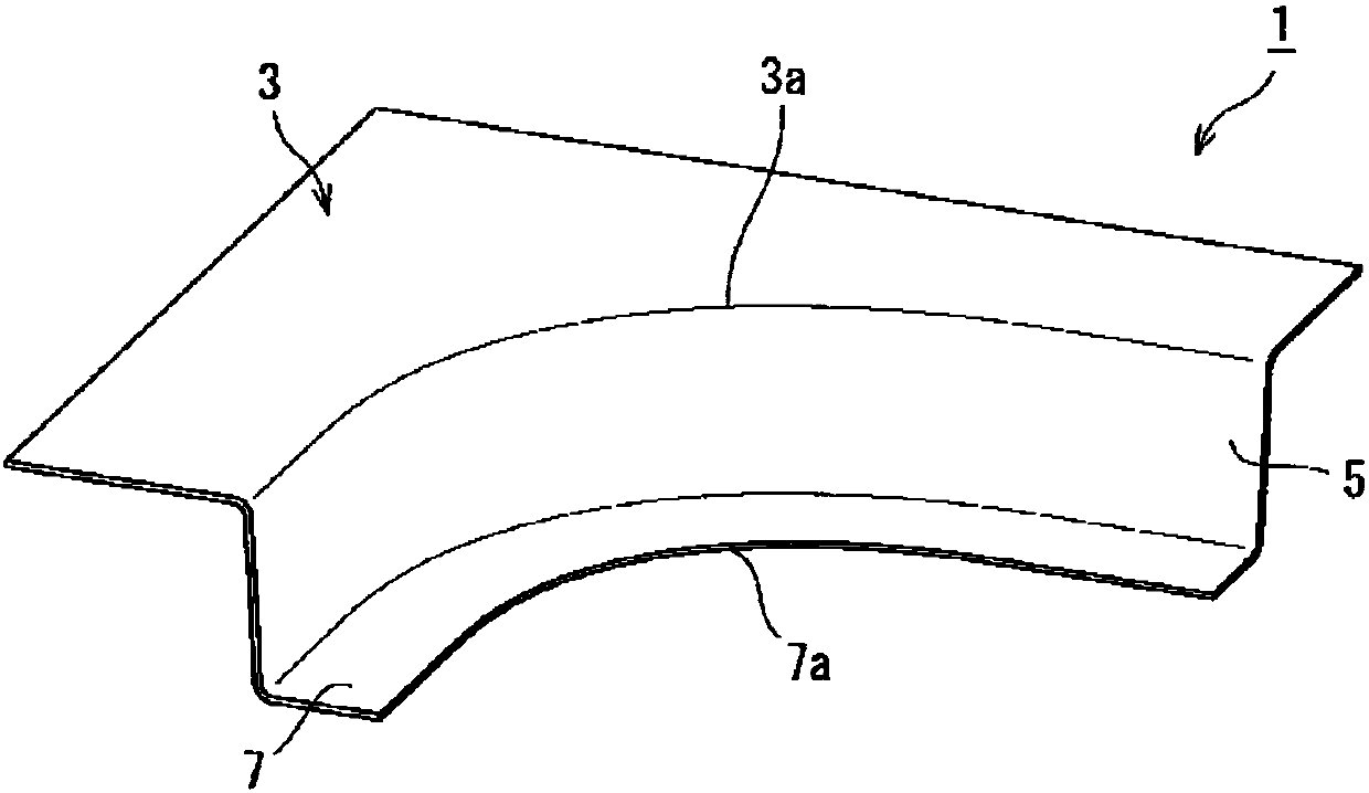
[0145] Furthermore, as Example 1, the presence or absence of the stepped portion 8 was evaluated at the flange portion forming position.

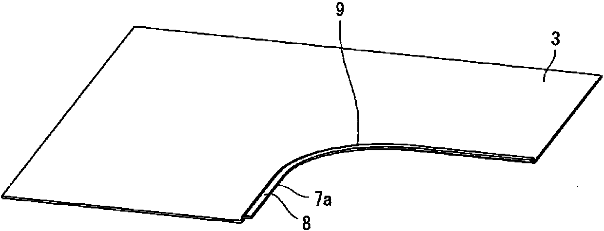
[0146]In Example 1, regarding the above-mentioned two members, it was evaluated whether there was a stepped portion 8 along the second concave outer peripheral edge portion 7a at the position where the flange portion 7 was formed, and whether there was no difference at the position where the flange portion 7 was formed. Whether stretch flange cracking occurs along the stepped portion 8 of the second concave outer peripheral edge portion 7a.

[0147] The method of determining the ridgeline 9 of the stepped portion 8 is determined by the above-mentioned first determination method and second determination method.

[0148] Furthermore, in the case of the stepped portion 8 having the stepped portion 8, the first ridgeline 9A is set at a straight line perpendicular to the central line 23 at a distance of 30 mm from the second concave outer periph...

Embodiment 2

[0155] As Example 2, the position of the first ridgeline 9A was evaluated.

[0156] In Example 2, regarding the above-mentioned two members as objects, in the case of having the stepped portion 8, according to the distance from the concave outer peripheral portion when the first ridgeline 9A is set on the stepped portion 8, whether The occurrence of tensile flange cracking was evaluated.

[0157] At this time, the second ridgeline 9B coincides with the reference line 22, and the step height is uniformly 5 mm.

[0158] Table 2 shows the evaluation results.

[0159] [Table 2]

[0160]

[0161] From Table 2, it is estimated that stretch flange cracking occurs when the set position of the first ridgeline 9A formed in the second step deviates from the second concave outer peripheral portion 7a by 20 mm to 50 mm.

[0162] It is considered that when the first ridgeline 9A is set to be 20 mm or less, since the stepped portion 8 is formed near the second concave outer peripheral ...

Embodiment 3

[0164] As Example 3, the effect by the position of the second ridgeline 9B was evaluated.

[0165] In Example 3, regarding the above-mentioned two members as objects, in the case of having the stepped portion 8, it was evaluated whether or not a pull occurred based on the amount by which the position of the second ridgeline 9B of the step was shifted to the left and right from the reference line 22. Flange cracked.

[0166] At this time, the position of the first ridgeline 9A was set to be 30 mm away from the second concave outer peripheral portion 7 a, and the step height was uniformly set to 5 mm.

[0167] Table 3 shows the evaluation results.

[0168] [table 3]

[0169]

[0170] As can be seen from Table 3, it was evaluated that stretch flange cracking occurred when the second ridgeline 9B was deviated from the reference line 22 by more than ±5 mm by the molding in the second step.

[0171] This can be presumed to be: when the inward deviation from the reference line ...


PUM

PropertyMeasurementUnit
strengthaaaaaaaaaa

Abstract

The present invention suppresses stretch flange breakage when manufacturing a stretch flange molded component manufactured with stretch flange molding. Provided is a manufacturing method that manufactures the stretch flange molded component provided with a top plate part (3) that has a first recessed outer peripheral edge part (3a) and a flange part (7) that is continuous with a vertical wall part(5), curved to a top plate part (3) side, and has a second recessed outer peripheral edge part (7a), wherein a step shaped part (8) is formed curved in the direction of the plate thickness with a crest line (9) extending along the second recessed outer peripheral edge part (7a) so as to surround the second recessed outer peripheral edge part (7a) in a position which becomes the flange part (7).

Description

technical field [0001] The present invention relates to a technique for producing a stretch flange forming part that is accompanied by stretch flange molding by having a concave outer peripheral edge portion bent so that a part of the outer peripheral edge is recessed inward on a top plate portion. Manufacture the flange. [0002] As such a stretch flange forming part, for example, a press-formed part used as a body frame part of an automobile, which has an L-shaped portion or a T-shaped portion in plan view, can be exemplified. In particular, the present invention is a preferable technology in the case of using an ultra-high-strength material of 980 MPa or higher as a raw material and producing it by press molding. Background technique [0003] The L-shaped part (refer to Figure 11 ) or T-shaped part (refer to Figure 12 ) parts, drawing and bending are generally used. [0004] Deep drawing is a method that usually uses a mold consisting of a punch, a die, and a wrinkle...

Claims


Application Information

Patent Timeline
Patent Type & Authority Applications(China)
IPC IPC(8): B21D19/08B21D22/26B21D53/88
CPCB21D19/08B21D22/26B21D53/88
Inventor 三宅弘人新宫丰久佐藤健太郎山崎雄司
Owner JFE STEEL CORP
Why Eureka
Try Eureka