A kind of ditching equipment for vegetable planting

A vegetable and equipment technology, applied in the field of ditching equipment for vegetable planting, can solve problems such as wear and tear, achieve the effects of low energy consumption, prolong service life, and reduce friction

Active Publication Date: 2020-08-18
四川明峰农业开发有限公司
View PDF4 Cites 0 Cited by
  • Summary
  • Abstract
  • Description
  • Claims
  • Application Information

AI Technical Summary

Problems solved by technology

[0003] The purpose of the present invention is to provide a ditching device for vegetable planting, which is used to improve the problem that the existing ditching device is easily worn due to severe vibration during operation

Method used


Image

  • A kind of ditching equipment for vegetable planting
  • A kind of ditching equipment for vegetable planting
  • A kind of ditching equipment for vegetable planting

Examples


Embodiment 1

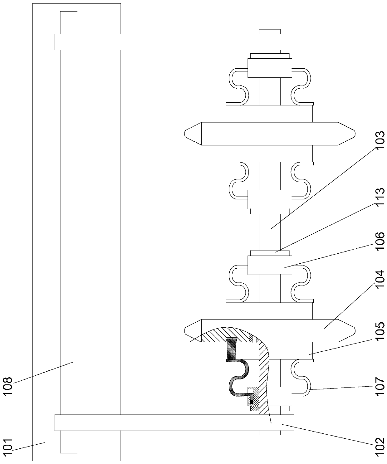
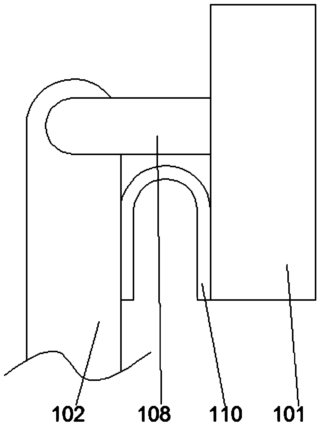
[0026] In order to facilitate the installation of the vertical beams, in this embodiment, preferably, a cross beam 108 is arranged on the mounting plate 101, and the upper end of the vertical beam 102 is connected to the cross beam 108 through a bearing in rotation. The mounting plate 101 is provided with a fixing plate 110, one end of the fixing plate 110 is fixedly connected to the mounting plate 101, and the other end of the fixing plate 110 is fixedly connected to the vertical beam 102 facing the On one side end surface of the mounting plate 101 . During installation, the two ends of the beam are fixedly connected to the mounting plate, and the upper end of the vertical beam is rotated and connected to the beam, so that the fixed plate connects the vertical beam and the mounting plate to each other. Under the action of the fixed plate and the beam, the overall structure is more stable. It is stable, and can improve the stability and firmness of the upper end of the vertica...

Embodiment 2

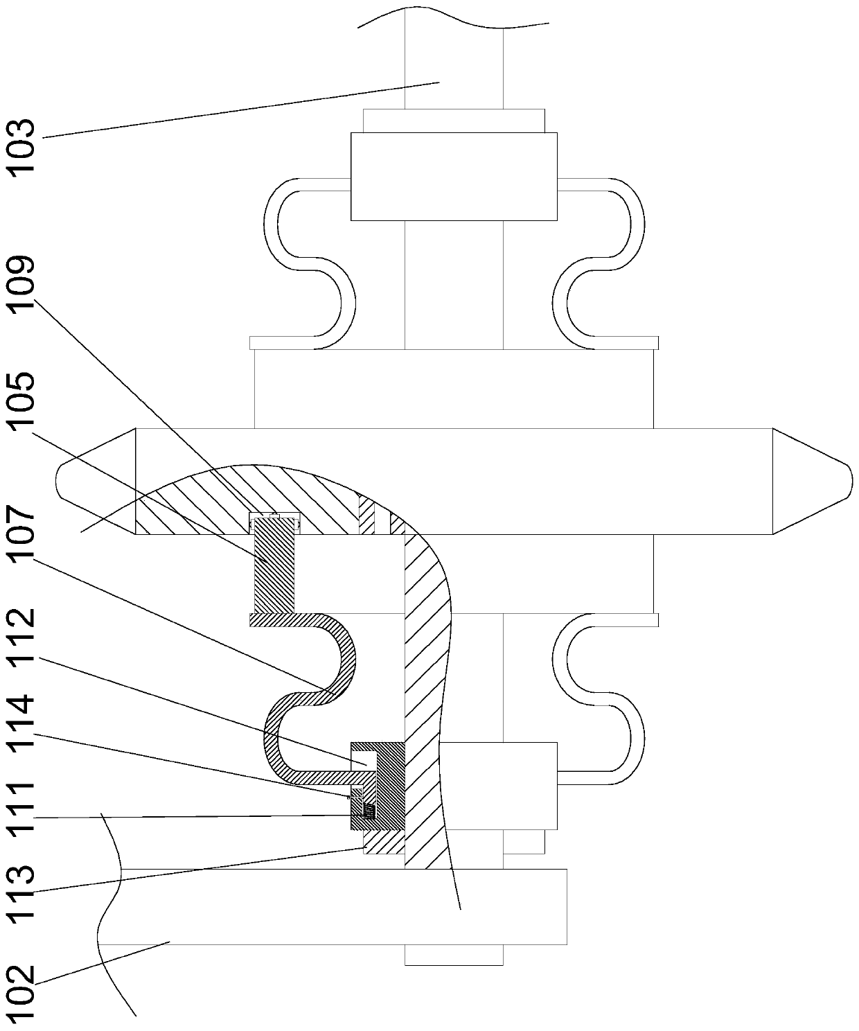
[0029] In this embodiment, in order to facilitate the installation of the legs, preferably, the outer wall of the outer tube 106 is provided with a fixing groove 112 with an L-shaped longitudinal section, and the ends of the legs 107 are L-shaped and can be plugged into The inner side of the fixing groove 112 . The fixing groove can be an annular groove centered on the axis of the outer tube. When installing, one end of the leg is fixed on the sleeve, and the other end of the leg is plugged into the fixing groove, which can facilitate the installation and disassembly of the leg. At the same time, it can Easy to adjust the outer tube.

[0030]In order to adjust the position of the outer tube according to needs, in this embodiment, preferably, the outer tube 106 is screwed on the central axis 103, and on the side of the outer tube 106 away from the support foot 107 A locking nut 113 is arranged on the central shaft 103 . After the position of the disc is determined, the outer ...

Embodiment 3

[0032] In this embodiment, on the basis of Embodiment 2, in order to improve the stability of the feet, preferably, a threaded hole communicating with the fixing groove 112 is provided on the outer wall of the outer tube 106, and in the threaded hole A locking bolt 114 is provided, and a strip-shaped counterbore is provided on the support foot 107 , and the end of the locking bolt 114 abuts against the counterbore on the support foot 107 . During installation, after inserting the end of the leg into the fixing groove, tighten the locking bolt into the threaded hole on the outer tube. At this time, when the end of the locking bolt is inserted into the counterbore on the leg, the leg cannot Move axially along the outer tube. The length direction of the counterbore can be parallel to the width direction of the support foot, and the strip-shaped counterbore can facilitate the positioning of the locking bolt. The end of the support leg is fixed by the locking bolt, which can preve...


PUM


Abstract

The invention discloses ditching equipment for vegetable cultivation. The ditching equipment for vegetable cultivation comprises a mounting plate and two vertical beams arranged at the lower parts ofthe two ends of the mounting plate, a center shaft is arranged between the two vertical beams, a disc is arranged on the center shaft and is rotatably connected on the center shaft through a knuckle bearing, outer tubes are respectively arranged on the center shaft on the two sides of the disc, sleeves are respectively arranged on the two sides of the disc, a plurality of evenly distributed supporting feet are arranged between the sleeve and the outer tube, the middle part of the supporting foot is bent into an S-shape, an annular locating groove corresponding to the sleeve in position is arranged on the side wall on each of the two sides of the disc, one side of the supporting foot far from the sleeve is connected on the inner side of the locating groove in an inserted manner, and universal balls are respectively arranged on the three end faces, located at one end of the inner side of the locating groove, of the sleeve. The ditching equipment improves the problem that the existing ditching equipment is easy to wear because of the violent vibration.

Description

technical field [0001] The invention relates to the field of vegetable cultivation, in particular to a ditching device for vegetable cultivation. Background technique [0002] When planting vegetables, in order to facilitate management and sowing, it is necessary to pre-drill trenches. Existing ditching equipment is large-scale equipment. During operation, when the hardness of the soil is high or there are hard stones in the soil, the ditching equipment is prone to wear due to severe vibration, and some ditching equipment is prone to damage. . Contents of the invention [0003] The purpose of the present invention is to provide a ditching device for vegetable planting, which is used to improve the problem that the existing ditching device is easily worn due to severe vibration during operation. [0004] The technical scheme adopted by the present invention is as follows: a ditching device for vegetable planting, comprising a mounting plate and 2 vertical beams arranged u...

Claims


Application Information

Patent Timeline
Patent Type & Authority Patents(China)
IPC IPC(8): A01C5/06
CPCA01C5/064
Inventor 李明
Owner 四川明峰农业开发有限公司
Why Eureka
Try Eureka