Lamp protection device and display screen

A technology of protection device and display screen, applied in the field of display screen, can solve the problem of lamp beads falling off due to impact, and achieve the effect of avoiding falling off, good effect and simple structure

Pending Publication Date: 2018-12-21
SHENZHEN ABSEN OPTOELECTRONIC CO LTD +1
View PDF0 Cites 2 Cited by
  • Summary
  • Abstract
  • Description
  • Claims
  • Application Information

AI Technical Summary

Problems solved by technology

[0004] The object of the present invention is to provide a lamp protection device and a display screen, aiming to solve the problem in the prior art that the lamp beads at the edge of the display screen are easy to be knocked off due to the removal of the protective plate during the splicing process of adjacent display screens. technical problem

Method used


Image

  • Lamp protection device and display screen
  • Lamp protection device and display screen
  • Lamp protection device and display screen

Examples


Embodiment 1

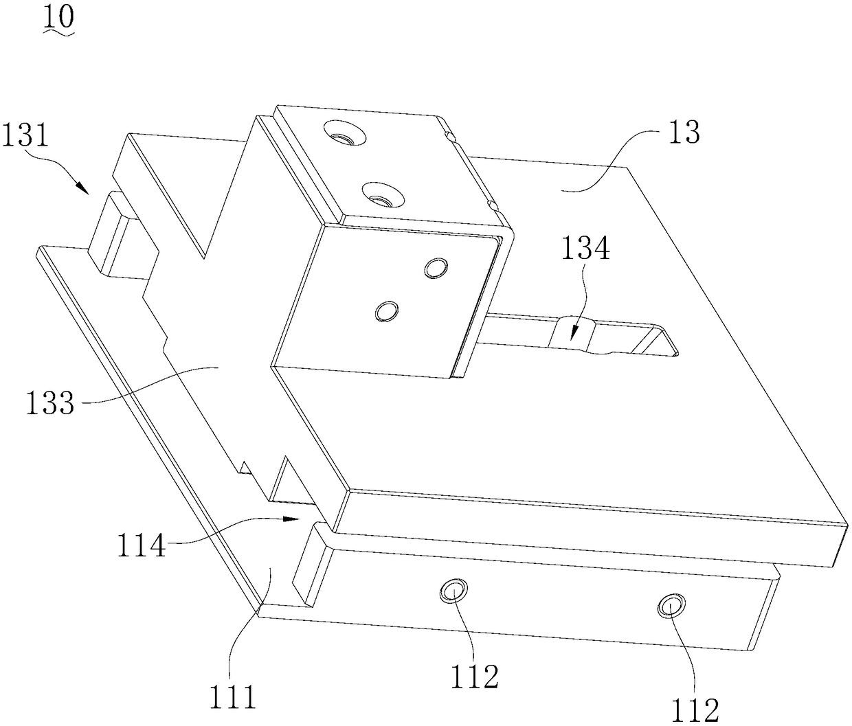
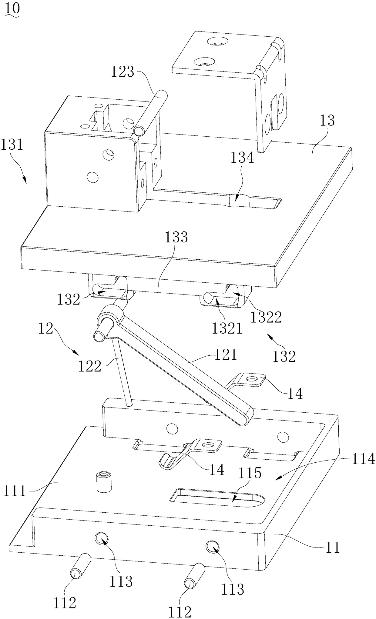
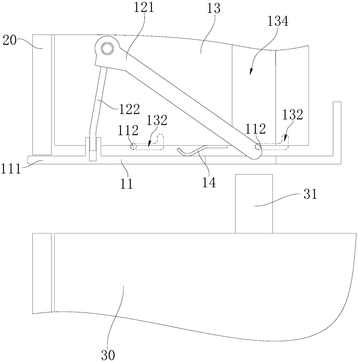
[0032] Such as Figure 1-8 As shown, the embodiment of the present invention provides a light protection device 10, which includes a protective cover 11, a driving mechanism 12 and a mounting part 13. One side of the mounting part 13 is provided with a display screen position 131, and the protective cover 11 is provided with On the side of the mounting part 13 adjacent to the display screen position 131, and the side of the protective cover 11 is provided with a protection protrusion 111 extending to the side of the display screen position 131; the driving mechanism 12 is installed on the mounting part 13, the driving mechanism 12 is connected with the protective cover 11 for driving the protective cover 11 to move, and there is a device between the protective cover 11 and the mounting part 13 The limiting mechanism is used to guide the protective cover 11 to move in a direction parallel to the bottom surface of the protective cover 11 and facing away from the protective protr...

Embodiment 2

[0059] The difference between this embodiment and Embodiment 1 is that the driving mechanism in this embodiment includes a driving rod and a connecting piece, the driving rod includes a fixed end and a free end oppositely arranged, the fixed end of the driving rod is hinged to the mounting part, and the connecting part is Vertically arranged, the upper end of the connecting piece is fixedly connected with the driving rod, the lower end of the connecting piece is hinged with the protective cover 11, and the free end of the moving driving rod drives the driving rod to rotate and then drives the protective cover 11 to move through the connecting piece. Specifically, the fixed end of the driving rod is hinged on the mounting part 13, and the upper end of the connecting part is fixedly connected to the driving rod, and the lower end of the elastic part is fixedly connected to the protective cover 11. By rotating the second end of the driving rod, the connecting part rotates, Then dr...

Embodiment 3

[0062] The difference between this embodiment and Embodiment 1 is that the driving mechanism in this embodiment includes a connecting rod and a running wheel, the running wheel is rotatably connected to the mounting part, one end of the connecting rod is hinged to the running wheel, and the other end of the connecting rod is connected to the protective The cover 11 is hinged so that the driving wheel rotates to drive the protective cover 11 to move through the connecting rod. Specifically, the running wheel is hinged on the mounting part 13, and the two ends of the connecting rod are respectively hinged on the running wheel and the protective cover 11. By turning the running wheel, the connecting rod is driven to move, and then the protective cover 11 is driven to move along a direction parallel to the protective cover. The bottom surface of the cover 11 moves in a direction away from the protection protrusion 111 in a straight line.

[0063] The rest of this embodiment is the...


PUM


Abstract

The invention belongs to the technical field of display screens, and particularly relates to a lamp protection device and a display screen. The lamp protection device comprises a protection cover, a driving mechanism and an installation piece. A display screen position is arranged on one side of the installation piece. The protection cover is arranged on the side, adjacent to the display screen position, of the installation piece. A protection protrusion extending to one side of the display screen position is arranged on one side of the protection cover. The driving mechanism is installed on the installation piece and connected with the protection cover to be used for driving the protection cover to move. A limiting mechanism for guiding the protection cover to move in the direction parallel to the bottom face of the protection cover and away from the protection protrusion is arranged between the protection cover and the installation piece. The lamp protection device is simple in structure and easy to operate and has a good effect of protecting lamp beads on the edge of the display screen.

Description

technical field [0001] The invention belongs to the technical field of display screens, in particular to a lamp protection device and a display screen. Background technique [0002] For display screens, especially in display screen rental scenarios, the proportion of lamp beads falling off and failing at the edge of the display screen is particularly large, and the failure of the lamp beads at the edge of the display screen directly affects the display effect of the display screen. With the popularization of small-pitch display screens, the assembly time of small-pitch display cabinets is getting smaller and smaller, especially for small-pitch display screens, because the welding area is correspondingly reduced, and the welding strength is also generally reduced. The probability of the lamp bead being hit and failing also increases significantly. [0003] At present, in order to prevent the lamp beads at the edge of the display screen from being hit, generally the side of t...

Claims


Application Information

Patent Timeline
IPC IPC(8): G09F9/30G09F9/302H05K5/02
CPCH05K5/0217G09F9/30G09F9/3026H05K5/03
Inventor 周洪贵娄小波
Owner SHENZHEN ABSEN OPTOELECTRONIC CO LTD
Why Eureka
Try Eureka