Automatic hot water stirring cup

A technology of automatic stirring and hot water, applied in the field of water cups, can solve the problem that the water cup does not have a cooling function, etc., to achieve the effect of easy cleaning and fast heat dissipation

Active Publication Date: 2018-02-23
苏州心工匠电子科技有限公司
View PDF0 Cites 14 Cited by
  • Summary
  • Abstract
  • Description
  • Claims
  • Application Information

AI Technical Summary

Problems solved by technology

[0002] There are many kinds of existing water cups, each with its own characteristics. According to the material, it can be divided into: ceramic cups, glass cups, plastic cups, stainless steel cup

Method used


Image

  • Automatic hot water stirring cup
  • Automatic hot water stirring cup
  • Automatic hot water stirring cup

Examples


Embodiment 1

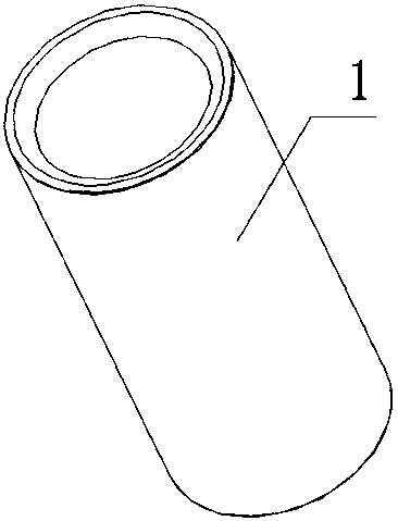
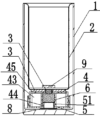
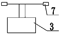
[0024] Such as Figure 1-3 As shown, a hot water automatic stirring cup includes a cup body 1, an inner container 2, the upper part of the inner container 2 is connected with the inner container 1, and a storage space is formed between the inner container 2 and the side wall and the bottom of the cup body 1. Cavity; one side of the power generation piece 3 is connected to the bottom outer surface of the inner tank 2, and the other side of the power generation piece 3 is connected to the upper surface of the metal cup bottom cover 4; the cup bottom 5 made of metal or plastic material is connected to the cup bottom cover 4, the cup bottom 5 and the cup bottom cover 4 form a heat-conducting medium accommodation chamber, and the heat-conducting medium is installed in the heat-conducting medium accommodation chamber; the motor 6 is arranged in the cup bottom cover 4, and the power generation piece 3 is provided with a through hole. The motor 6 is installed through the generator she...

Embodiment 2

[0031] The difference between this embodiment and Embodiment 1 is that in this embodiment, the motor is arranged under the power generating sheet, and no hole is needed in the middle of the generating sheet. The specific structure is as follows:

[0032] A hot water automatic stirring cup, comprising a cup body 1, an inner container 2, the upper part of the inner container 2 is connected with the cup body 1, and a receiving cavity is formed between the inner container 2 and the side wall and bottom of the cup body 1; One side of the sheet 3 is connected to the bottom outer surface of the inner tank 2; the other side of the power generation sheet 3 is connected to the upper surface of the metal cup bottom cover 4; the cup bottom 5 is connected to the bottom of the cup bottom cover 4, and the cup bottom 5 and the cup bottom cover 4 Form a heat-conducting medium accommodating chamber, and the heat-conducting medium is installed in the heat-conducting medium accommodating chamber;...


PUM


Abstract

An automatic hot water stirring cup comprises a cup body and a liner, the upper portion of the liner is connected with the cup body, a containing cavity is formed among the liner, the side wall of thecup body and the bottom of the cup body, one surface of a power generating piece is connected on the outer surface of the bottom of the liner, the other surface of the power generating piece is connected on the upper surface of a metal cup bottom cover, a cup bottom is connected on the lower portion of the cup bottom cover, the cup bottom and the cup bottom cover form a heat-conducting medium containing chamber, a heat-conducting medium is stored into the heat-conducting medium containing chamber, a motor is arranged in the cup bottom cover, the power generating piece is connected with the motor through a PCB (printed circuit board), a shaft of the motor is connected with a magnet, a magnet is arranged at the position corresponding to the inner surface of the bottom of the liner, and themotor drives the magnets to rotate to generate magnetic force, so that water is stirred. The power generating piece of the cup generates power by the aid of the temperature difference of hot water todrive the motor to rotate, the magnet is connected on the shaft of the motor, the motor drives the magnets to rotate to generate the magnetic force, water in the cup is stirred, stirring and cooling are achieved, the integrity of the liner is not broken, and cleaning is facilitated.

Description

technical field [0001] The invention relates to the technical field of water cups, in particular to a hot water automatic stirring cup. Background technique [0002] There are many kinds of existing water cups, each with its own characteristics. According to the material, it can be divided into ceramic cups, glass cups, plastic cups, stainless steel cups, etc.; according to the structure, it can be divided into: single-layer water cups, double-layer water cups, etc. function of keeping warm; but these traditional cups do not have a cooling function. In the prior art, the water temperature in the water cup is lowered. The method adopted is that the water cup is provided with a water exchange tank on the outer layer. After pouring hot water into the cup, if the hot water needs to be cooled, just inject it into the water exchange tank. Tap water, the outer heat exchange tank can cool the hot water in the water cup, so that when people are very thirsty, they can drink boiled wa...

Claims


Application Information

Patent Timeline
IPC IPC(8): A47G19/22A47G23/04
CPCA47G19/2205A47G19/2288
Inventor 董政
Owner 苏州心工匠电子科技有限公司
Why Eureka
Try Eureka