AI technical title is built by Patsnap AI team. It summarizes the technical point description of the patent document.
A technology of brackets and arch wire slots, which is applied in the field of brackets and self-locking brackets, can solve the problems of affecting the treatment effect, easy to wear pins, and loss of arch wire fixing ability, etc., so as to avoid damage and uniform force Effect
Active Publication Date: 2018-02-23
GUANGZHOU OO MEDICAL SCI LTD
View PDF6 Cites 6 Cited by
Summary
Abstract
Description
Claims
Application Information
AI Technical Summary
This helps you quickly interpret patents by identifying the three key elements:
Problems solved by technology
Method used
Benefits of technology
Problems solved by technology
Due to the narrow and long sliding groove of this locking structure, the pins are easy to wear during the process of opening the cover, and the wall of the elastic arm is relatively short, resulting in a decrease in the self-locking force of the cover, making the cover very easy or automatic to open, thereby losing alignment. wire fixation
Moreover, the existing bracket cover locking structure cannot arbitrarily adjust the size of the locking force, and cannot provide a large self-locking force, which affects the treatment effect
Method used
Image
Click on the blue label to locate the original text in one second.
Reading with bidirectional positioning of images and text.
Examples
Embodiment 1
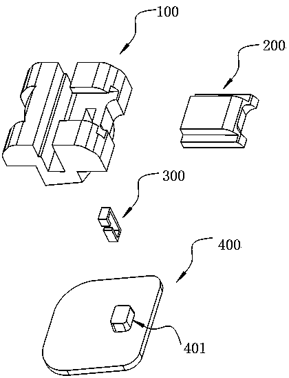
[0038] see figure 1 , is an exploded exploded view of the bracket, the bracket includes a bracket body 100 , a cover 200 , an elastic member 300 and a bottom plate 400 , and the bottom plate 400 is provided with a boss 401 .
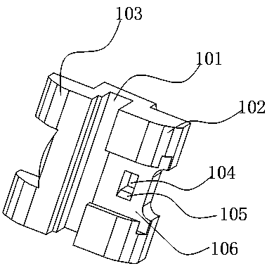
[0039] see figure 2 The top of the bracket main body 100 is provided with an archwire slot 101, the archwire slot 101 divides the bracket main body 100 into a first end 102 and a second end 103, and the top of the first end 102 is provided with a T-shaped slot 106 , a placement hole 104 is provided at the bottom of the T-shaped slot 106, the placement hole 104 penetrates to the bottom end of the bracket main body 100, and a T-shaped slot is provided on the side of the placement hole 104 perpendicular to the groove direction of the archwire slot 101. The bottom begins to extend to the escape position 105 inside the placement hole 104 .
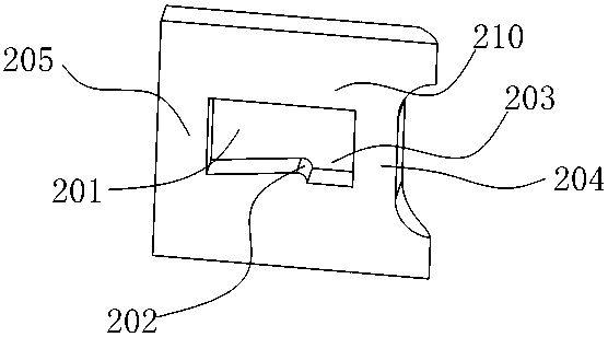
[0040] see image 3 , Figure 4 , is the cover body 200, the bottom surface of the cover body 200 is provided with...
Embodiment 2
[0047] See Figure 9 , the archwire slot 101 is in the closed position, and the elastic member 300 is arranged laterally. At this time, the sliding protrusion 202 of the cover body 200 is arranged on the top end of the cover body 200. When the archwire slot 101 is opened, the sliding protrusion 202 is pressed against the elastic member 300 , the downward pressure applied to the elastic member 300 forces the upper end 311 and the lower end 312 at the notch 301 of the elastic member 300 to approach each other, and the principle is the same as that of the first embodiment.
[0048] See Figure 10 , are three differently deformed elastic members 300, which are respectively in the natural state, the state of the compression process, or the state after compression, where Figure A is in three states, the natural state, the state of the compression process, the state after compression, and the elastic member 300 after compression In a closed-loop state, it can withstand a large force...
PUM
Abstract
The invention discloses a bracket. The bracket comprises a bracket body, a cover body, an elastic part and a bottom plate, wherein the bracket body is provided with an arch wire groove in a penetrating way; the bottom plate is arranged at the bottom part of the bracket; the cover body is glidingly matched with the top part of the bracket body, and is used for opening or closing the arch wire groove; a slide bulge is arranged on the cover body, and the elastic part is arranged on the bracket body; the slide bulge is in contact with the elastic part, and is used for extruding the elastic part when the cover body is slide; the elastic part is provided with a notch. The bracket has the advantages that by arranging the elastic part with the notch, the larger locking force can be produced on thecover body, the stress is uniform, and the cover body can be tightly fixed; the size of the notch can be adjusted, so that the self-locking force can be adjusted, and the different self-locking forceis set between different brackets at different tooth positions; the elastic part does not extrude the bracket body and the cover body in the deformation process, so that the damage to the elastic part is avoided.
Description
technical field [0001] The invention designs the fields of fixed orthodontic technology and tooth orthodontics, and in particular relates to brackets and bracket self-locking methods. Background technique [0002] Bracket is an important part of fixed orthodontic technology. It is an appliance for correcting tooth alignment deformity. The archwire exerts various types of orthodontic force on the teeth through the bracket. The main function of the bracket is to fix the archwire. In this way, the arch wire can play a better role and transmit the orthodontic force, so as to control the three-dimensional movement of the teeth and achieve the purpose of orthodontic treatment. [0003] The bracket cover is used to fix the arch wire, and the bracket cover is locked and positioned by a locking structure. [0004] The existing locking structure of the bracket cover is to open a groove at the bottom of the cover and use the external pin to fix the cover to realize positioning and loc...
Claims
Application Information
Patent Timeline
Application Date:The date an application was filed.
Publication Date:The date a patent or application was officially published.
First Publication Date:The earliest publication date of a patent with the same application number.
Issue Date:Publication date of the patent grant document.
PCT Entry Date:The Entry date of PCT National Phase.
Estimated Expiry Date:The statutory expiry date of a patent right according to the Patent Law, and it is the longest term of protection that the patent right can achieve without the termination of the patent right due to other reasons(Term extension factor has been taken into account ).
Invalid Date:Actual expiry date is based on effective date or publication date of legal transaction data of invalid patent.

