Oil paint spraying device

A spraying device and paint technology, applied in the direction of spraying devices, etc., can solve the problems of not being able to adjust according to the needs of the staff, the lack of color types of oily paints, and the poor comfort of the push rod, so as to reduce the use limit Sexuality, various colors, and the effect of improving the comfort of the hand

Inactive Publication Date: 2018-02-23
JIANGSU KANGJIE MACHINERY
View PDF0 Cites 3 Cited by
  • Summary
  • Abstract
  • Description
  • Claims
  • Application Information

AI Technical Summary

Problems solved by technology

[0002] As we all know, the oil-based paint spraying device is an auxiliary device used to spray oil-based paint onto the outer wall of the material during the coloring process to make it better colored. It has been widely used in the field of material coloring. The use of; Existing oily paint spraying device comprises base plate, connecting rod, push rod, four groups of supports and four groups of rollers, and the bottom end of connecting rod is installed on the left side of base plate top, and push rod is installed on the top of connecting rod, four The tops of the group brackets are respectively installed on the left front side, right front side, left rear side and right rear side of the bottom of the bottom plate. There is a working cavity inside, the top of the working box is connected with a feed port, and a cover is provided at the feed port, and a liquid outlet pipe is connected to the lower right side of the work box; when the existing oily paint spraying device is used, Move the working box to a suitable position through the push rod, introduce the oily paint into the working chamber through the feed port, and spray it through the liquid outlet pipe; it is found in the use of the existing oily paint spraying device that the push rod The height is fixed and cannot be adjusted according to the needs of the staff, resulting in poor adaptability; and there are fewer types of oil-based paints, resulting in higher limitations in use; and the poor grip comfort of the push rod, resulting in its less practical

Method used


Image

  • Oil paint spraying device
  • Oil paint spraying device

Examples


Embodiment Construction

[0013] The specific implementation manners of the present invention will be further described in detail below in conjunction with the accompanying drawings and embodiments. The following examples are used to illustrate the present invention, but are not intended to limit the scope of the present invention.

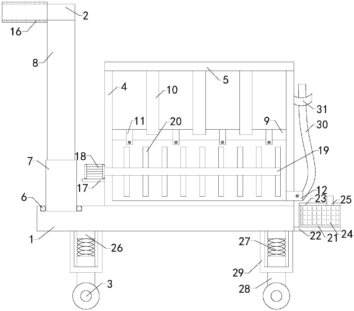
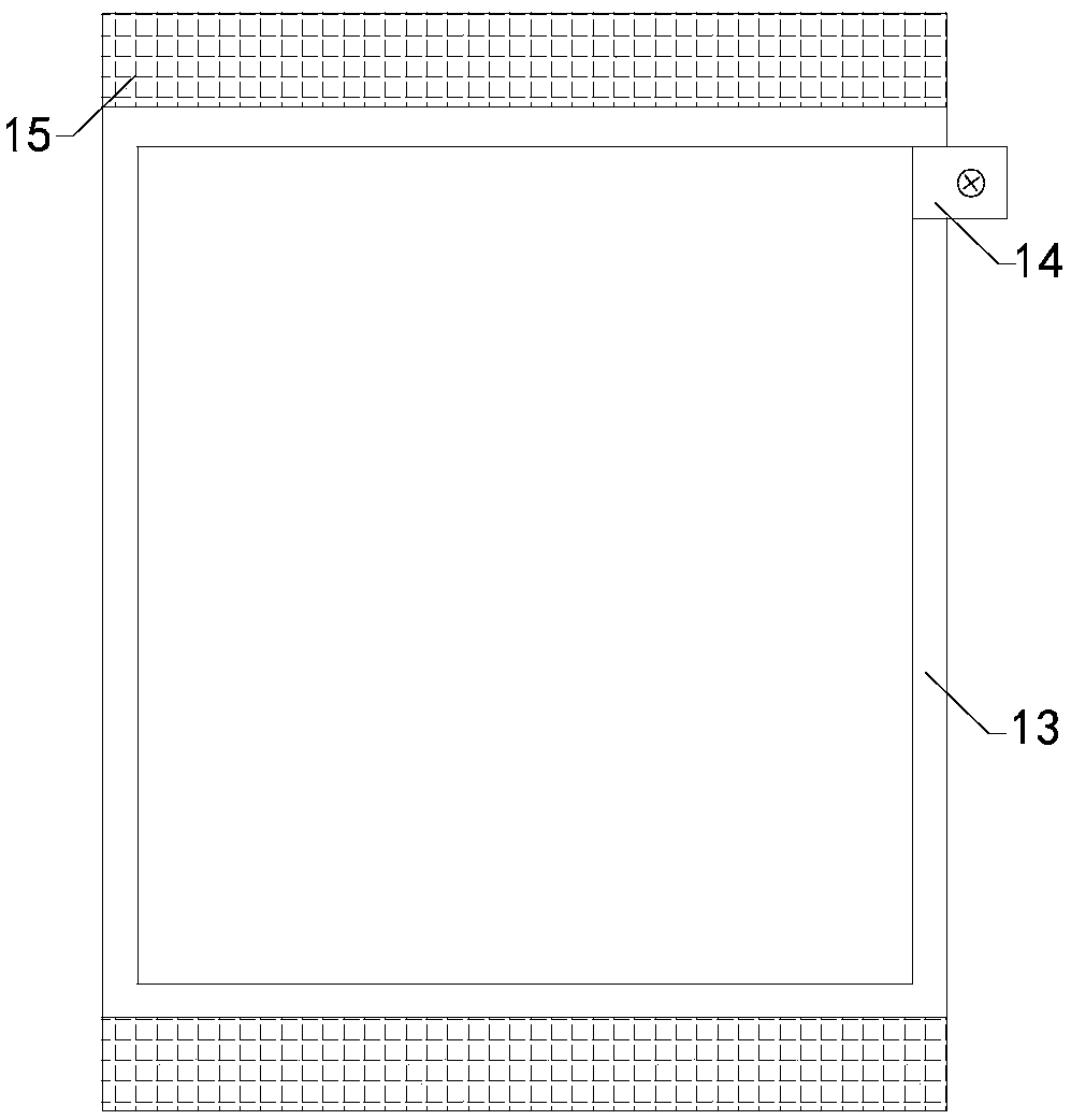
[0014] Such as figure 1 and figure 2 As shown, a kind of oily paint spraying device of the present invention comprises base plate 1, connecting rod, push rod 2, four sets of brackets and four sets of rollers 3, also includes work box 4, and work box is installed on the base plate, inside the work box There is a working cavity, the top of the working box is connected with a feed inlet, and a cover 5 is arranged at the feed inlet; a placement groove is arranged on the left side of the top of the bottom plate, and a ball bearing 6 is arranged inside the placement groove, and the connecting rod includes The electric cylinder 7 and the telescopic rod 8, the bottom end of the...


PUM


Abstract

The invention relates to the technical field of paint vehicle spraying accessory devices, in particular to an oil paint spraying device. The height of a push rod of the oil paint spraying device can be adjusted according to the needs of workers, and the adaptive capacity of the oil paint spraying device is improved; the variety of oil paint colors is added, so that the use limitation of the oil paint spraying device is reduced; and the grip comfort level of the push rod is improved, so that the practicability of the oil paint spraying device is improved. The oil paint spraying device comprisesa bottom plate, a connecting rod, the push rod, four sets of supports and four sets of idler wheels, and further comprises a work box which is installed on the bottom plate. A working chamber is formed in the work box, a feed port communicates with and is arranged at the top end of the work box, and a blocking cover is arranged at the feed port. A containing groove is formed in the left side of the top end of the bottom plate, and ball bearings are arranged in the containing groove. The connecting rod comprises an electric air cylinder and a telescopic rod. The oil paint spraying device further comprises a lower separation plate, three sets of upper separation plates and a massage cushion, a pick and place pipe communicates with and is arranged on the massage cushion, magic stickers are arranged at the top end and the bottom end of the massage cushion, and massage protrusions are arranged on the outer sidewall of the massage cushion.

Description

technical field [0001] The invention relates to the technical field of paint spraying attachments, in particular to an oily paint spraying device. Background technique [0002] As we all know, the oil-based paint spraying device is an auxiliary device used to spray oil-based paint onto the outer wall of the material during the coloring process to make it better colored. It has been widely used in the field of material coloring. The use of; Existing oily paint spraying device comprises base plate, connecting rod, push rod, four groups of supports and four groups of rollers, and the bottom end of connecting rod is installed on the left side of base plate top, and push rod is installed on the top of connecting rod, four The tops of the group brackets are respectively installed on the left front side, right front side, left rear side and right rear side of the bottom of the bottom plate. There is a working cavity inside, the top of the working box is connected with a feed port,...

Claims


Application Information

Patent Timeline
Patent Type & Authority Applications(China)
IPC IPC(8): B05B13/00B05B12/10B05B15/25B05B15/65
CPCB05B12/14B05B13/005
Inventor 吴文杰吴进姜大林
Owner JIANGSU KANGJIE MACHINERY
Why Eureka
Try Eureka