Hot metal ladle and production line thereof

A technology for ladle and cover, which is applied in casting molten material containers, manufacturing tools, foundry workshops, etc., can solve the problems of no hook, uneven scattering, and large heat, and achieve the effect of improving efficiency.

Pending Publication Date: 2018-02-23
项刚
View PDF5 Cites 1 Cited by
  • Summary
  • Abstract
  • Description
  • Claims
  • Application Information

AI Technical Summary

Problems solved by technology

[0002] The molten iron tanks of iron and steel enterprises sit on the molten iron carts, and the 1500°C molten iron produced from ironmaking is transported to the converter for steelmaking by train, railway or automobile transportation. For more than 15 times, 3-4 molten iron ladles are required for each tapping. Whether it is in the state of filling molten iron or not, the mouth of the tank needs to radiate heat outward for 24 hours. In rainy and snowy weather, the heat loss will be greater. It is not environmentally friendly. In light cases, it reduces the amount of steel scrap added in steelmaking. In severe cases, it also causes the molten iron on the upper part of the molten iron tank to solidify and cover, which increases maintenance costs.
[0003] In response to this phenomenon, various companies are doing a lot of improvement work. 1. After tapping the iron, sprinkle carbonized rice husks on the molten iron tank to keep heat and reduce heat loss. High, the effect is not obvious, the cost is increased and it is not environmentally friendly, most companies do not use it
2. It is to install a simple opening and closing type capping device on some molten iron tank cars with large space, but for most complex places with small space, there is no way to implement capping. Adding a molten iron cover without a telescopic mechanism causes the height to exceed the molten iron tank Height, the cover cannot be opened when the blast furnace is tapping, and the hook cannot be hooked to the steelmaking crane; in addition, after opening, it exceeds the center line of the hook of the hot metal car, and 3-4 hot metal cars are connected together without removing the hook. In this way, it will not be possible to add a lid to the molten iron tank.
It leads to a huge waste of energy in iron and steel enterprises, and also increases the emission of atmospheric carbon dioxide

Method used


Image

  • Hot metal ladle and production line thereof
  • Hot metal ladle and production line thereof
  • Hot metal ladle and production line thereof

Examples


Embodiment 1

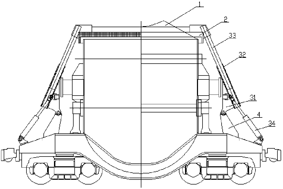
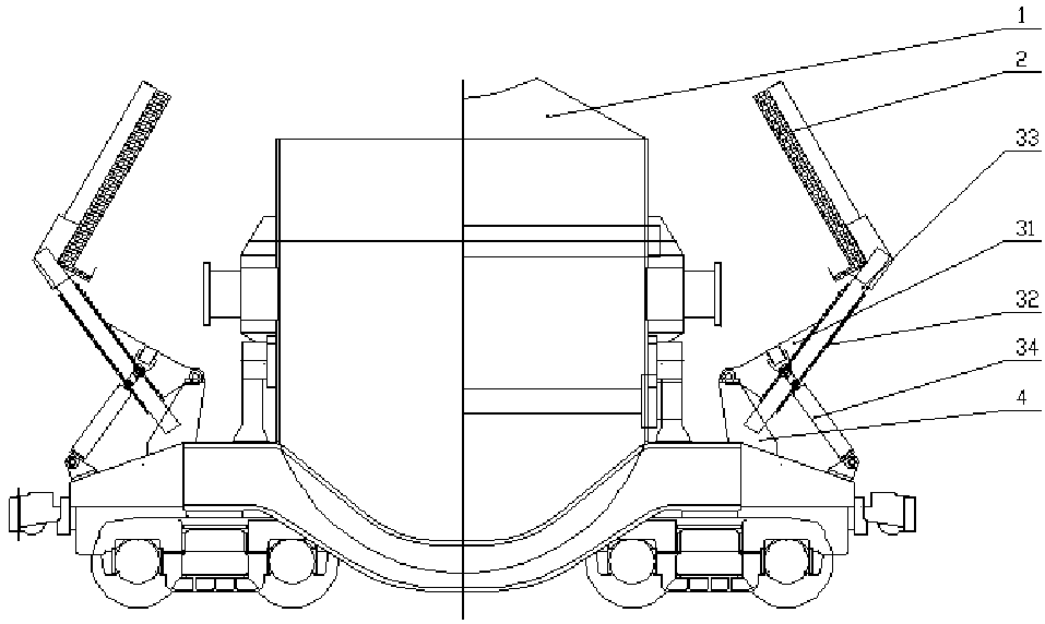
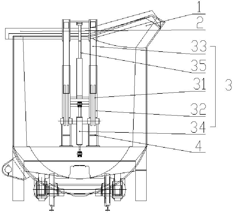
[0031] figure 1 A schematic structural view of the ladle provided by Embodiment 1 of the present invention; figure 2 for figure 1 Schematic diagram of the open state of the cover; image 3 for figure 1 side view of the Figure 1-Figure 3 As shown, the ladle provided by Embodiment 1 of the present invention includes a ladle body 1, a cover 2 and a lifting device 3;

[0032] The ladle body 1 upper cover is equipped with two said ladle covers 2, and said ladle body 1 is equipped with a lifting device 3 connected with each said ladle cover 2 respectively;

[0033] The lifting device 3 includes a rotating arm 31, a guide sleeve 32, a telescopic rod 33, a first telescopic thrust mechanism 34 and a second telescopic thrust mechanism 35, the rotating arm 31 is installed on the ladle body 1, and the guide The sleeve 32 is installed on the rotating arm 31, the telescopic rod 33 is installed in the guide sleeve 32, the telescopic rod 33 is connected with the cover 2, and the first ...

Embodiment 2

[0043] The ladle provided in this embodiment two is a further improvement to the ladle provided in embodiment one, in embodiment one and Figure 1-Figure 3 On the basis of the above, the ladle provided in the second embodiment includes a ladle body 1, a cover 2 and a lifting device 3;

[0044] The ladle body 1 upper cover is equipped with two said ladle covers 2, and said ladle body 1 is equipped with a lifting device 3 connected with each said ladle cover 2 respectively;

[0045] The lifting device 3 includes a rotating arm 31, a guide sleeve 32, a telescopic rod 33, a first telescopic thrust mechanism 34 and a second telescopic thrust mechanism 35, the rotating arm 31 is installed on the ladle body 1, and the guide The sleeve 32 is installed on the rotating arm 31, the telescopic rod 33 is installed in the guide sleeve 32, the telescopic rod 33 is connected with the cover 2, and the first telescopic thrust mechanism 34 is connected with the rotating arm 32. The arm 31 is co...

Embodiment 3

[0060] The ladle provided in this embodiment three is a further improvement to the ladle provided in embodiment one, in embodiment one and Figure 1-Figure 3 On the basis of the above, the ladle provided by the present embodiment three includes a ladle body 1, a cover 2 and a lifting device 3;

[0061] The ladle body 1 upper cover is equipped with two said ladle covers 2, and said ladle body 1 is equipped with a lifting device 3 connected with each said ladle cover 2 respectively;

[0062] The lifting device 3 includes a rotating arm 31, a guide sleeve 32, a telescopic rod 33, a first telescopic thrust mechanism 34 and a second telescopic thrust mechanism 35, the rotating arm 31 is installed on the ladle body 1, and the guide The sleeve 32 is installed on the rotating arm 31, the telescopic rod 33 is installed in the guide sleeve 32, the telescopic rod 33 is connected with the cover 2, and the first telescopic thrust mechanism 34 is connected with the rotating arm 32. The arm...


PUM


Abstract

The invention discloses a hot metal ladle. The hot metal ladle comprises a hot metal ladle body, ladle covers and lifting devices; the two ladle covers cover the hot metal ladle body, and the liftingdevices connected with the ladle covers respectively are mounted on the hot metal ladle body; each lifting device comprises a rotating arm, a guiding sleeve, a telescopic rod, a first telescopic thrust mechanism and a second telescopic thrust mechanism, wherein the rotating arms are mounted on the hot metal ladle body, the guiding sleeves are mounted on the rotating arms, the telescopic rods are mounted in the guiding sleeves and connected with the ladle covers, the first telescopic thrust mechanisms are connected with the rotating arms, one ends of the second telescopic thrust mechanisms areconnected with the ladle covers, and the other ends of the second telescopic thrust mechanisms are connected with the guiding sleeves. Field changes are small for tapping of various blast furnaces, itis unnecessary to modify a hook of a steelmaking hot metal ladle, after the ladle covers are opened to the position, both sides are not over the central line of a hook of a hot metal ladle vehicle, it is unnecessary to take down the hook during tapping and steelmaking transportation, and the efficiency is improved. On the basis of the hot metal ladle, the invention further provides a production line of the hot metal ladle.

Description

technical field [0001] The invention relates to the technical field of molten iron transportation, in particular to a molten iron ladle and a production line. Background technique [0002] The molten iron tanks of iron and steel enterprises sit on the molten iron carts, and the 1500°C molten iron produced from ironmaking is transported to the converter for steelmaking by train, railway or automobile transportation. For more than 15 times, 3-4 molten iron ladles are required for each tapping. Whether it is in the state of filling molten iron or not, the mouth of the tank needs to radiate heat outward for 24 hours. In rainy and snowy weather, the heat loss will be greater. It is not environmentally friendly. In the light case, it reduces the amount of steel scrap added in steelmaking. In the severe case, it also causes the molten iron on the upper part of the molten iron tank to solidify and cover, which increases the maintenance cost. [0003] In response to this phenomenon,...

Claims


Application Information

Patent Timeline
Patent Type & Authority Applications(China)
IPC IPC(8): B22D41/00B22D41/12B22D47/00
CPCB22D41/00B22D41/12B22D47/00
Inventor 项刚
Owner 项刚
Why Eureka
Try Eureka