Lifting type gantry laser cutting machine cross beam

A laser cutting machine and beam technology, applied in laser welding equipment, welding equipment, metal processing equipment, etc., can solve the problem that the synchronization of the rack and pinion transmission on both sides is difficult to control, increase the difficulty of on-site operators, and increase the economic cost of machine tools, etc. problems, to achieve the effects of improved controllable accuracy, short Z-axis travel, and uniform force

Pending Publication Date: 2018-02-23
WUHAN CARTER LASER ENG
View PDF6 Cites 4 Cited by
  • Summary
  • Abstract
  • Description
  • Claims
  • Application Information

AI Technical Summary

Problems solved by technology

[0003] The exchange table of the common gantry laser cutting machine in the current market adopts a three-dimensional structure, which is divided into upper and lower workbenches to realize non-planar exchange and cutting of plates. Movement, using servo motor plus rack and pinion transmission, so that the laser cutting head can extend along the Z-axis direction to cut the plate, and the Z-axis will be elongated during cutting, which will affect the cutting accuracy and cutting speed during fast cutting. At the same time, due to the Z The shaft stroke is relatively small, and the synchronization of the rack and pinion transmission on both sides is difficult to control
[0004] In order to ensure that the cutting head can cut the plate on the workbench within a limited and short stroke, at present, a liftable double-layer workbench is often used to make up for the lack of Z-axis travel. The disadvantages of the liftable workbench are obvious. To solve the problem of accurate lifting to the same height, the use of lifting structure also greatly increases the economic cost of the entire machine tool, and increases the difficulty of operation for on-site operators

Method used


Image

  • Lifting type gantry laser cutting machine cross beam
  • Lifting type gantry laser cutting machine cross beam

Examples


Embodiment Construction

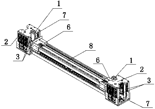
[0018] like figure 1 As shown, it is a schematic diagram of the overall structure of the beam of a liftable gantry laser cutting machine, including the lifting cylinder 1, the control beam lifter 2, the linear guide shaft 3, the zero point limit block 4, the oil pressure buffer 5, and the fixed beam support Plate 6, buffer rubber ring 7 and beam 8, the lifting cylinder 1, control beam lifter 2, linear guide shaft 3, zero point limit block 4, oil pressure buffer 5, fixed beam support plate 6 and buffer rubber ring 7 The left and right sides are evenly divided, the beam 8 is located in the middle position, and the left and right ends are respectively connected with the fixed beam support plate 6 by bolts, and the lifting air rod 1 in the control beam lifter 2 can drive the fixed beam support plate 6 and the beam 8 Lifting movement.

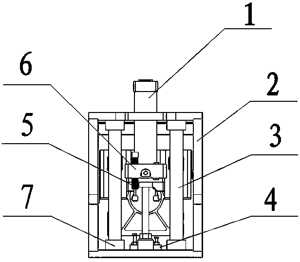
[0019] like figure 2 As shown, it is an end view of the beam of a liftable gantry laser cutting machine. The control beam lifter 2 is powered by...


PUM


Abstract

The invention discloses a lifting type gantry laser cutting machine cross beam which comprises lifting air cylinders, control cross beam lifters, linear guiding shafts, zero stop blocks, oil buffers,fixing cross beam supporting plates, buffer rubber rings and a cross beam part; the lifting air cylinders, the control cross beam lifters, the linear guiding shafts, the zero stop blocks, the oil buffers, the fixing cross beam supporting plates and the buffer rubber rings are arranged on the left side and the right side; the cross beam part is located in the middle; the left end and the right endof the cross beam part are fixedly connected with the fixing cross beam supporting plates through bolts correspondingly; and lifting air rods in the control cross beam lifters can drive the fixing cross beam supporting plates and the cross beam part to carry out lifting motion. The lifting type gantry laser cutting machine cross beam is simple in structure and convenient to operate; a laser knifehead of a cutting machine is driven to lift vertically through the lifting motion of the cross beam part, so that the problem that the stroke of the laser knife head in the Z axis is not sufficient issolved, the controllable precision of the laser cutting machining process is improved and the cutting speed is raised significantly.

Description

technical field [0001] The invention belongs to the field of laser cutting, and in particular relates to a beam of a liftable gantry laser cutting machine. Background technique [0002] As a new type of thermal cutting processing technology, laser cutting has many advantages such as fast cutting speed, high production efficiency and small thermal deformation area. It has become one of the main processing methods of metal sheets and has been widely used. At present, the laser cutting machine mainly includes a control system, a laser cutting head and a machine tool table. In actual work, the plate to be cut is placed on the machine tool table, and the laser cutting head controls the laser cutting head Determine a reference point by moving in the X, Y, and Z directions, and then determine the coordinates of the cutting tool according to the reference point, and then cut and shape the plate. [0003] The exchange table of the common gantry laser cutting machine in the current m...

Claims


Application Information

Patent Timeline
Patent Type & Authority Applications(China)
IPC IPC(8): B23K26/08B23K26/70
CPCB23K26/08B23K26/702
Inventor 陈章陈华安陈伟黄新星薛建坤
Owner WUHAN CARTER LASER ENG
Why Eureka
Try Eureka