

Pressing pin device
A technology for fixing devices and storage boards, which is applied in metal processing, metal processing equipment, manufacturing tools, etc. It can solve the problems that the ejector rod of the pressure pin is easily damaged, the fixing is not firm enough, and it is inconvenient to disassemble and install, so as to save replacement time and disassemble. The effect of simple and quick installation and convenient replacement
- Summary
- Abstract
- Description
- Claims
- Application Information
AI Technical Summary
Problems solved by technology
Method used
Image

Examples
Embodiment Construction
[0014] The following will clearly and completely describe the technical solutions in the embodiments of the present invention with reference to the accompanying drawings in the embodiments of the present invention. Obviously, the described embodiments are only some, not all, embodiments of the present invention.
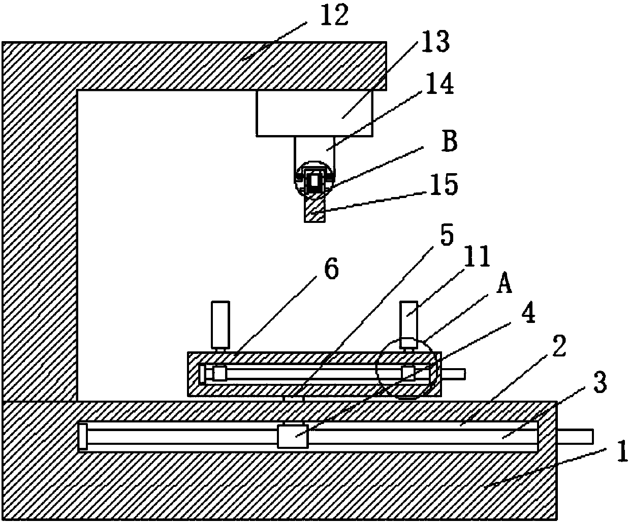
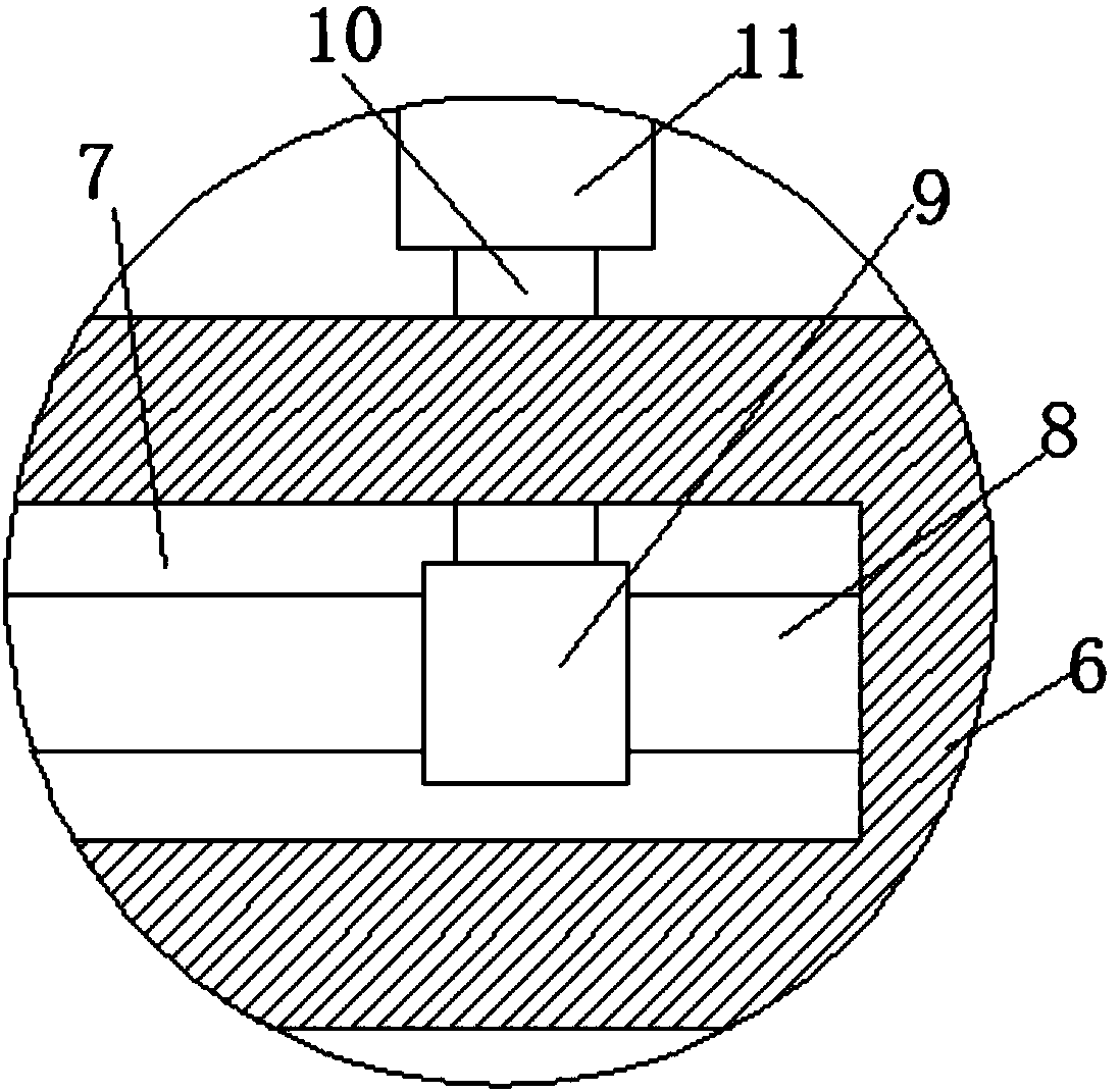
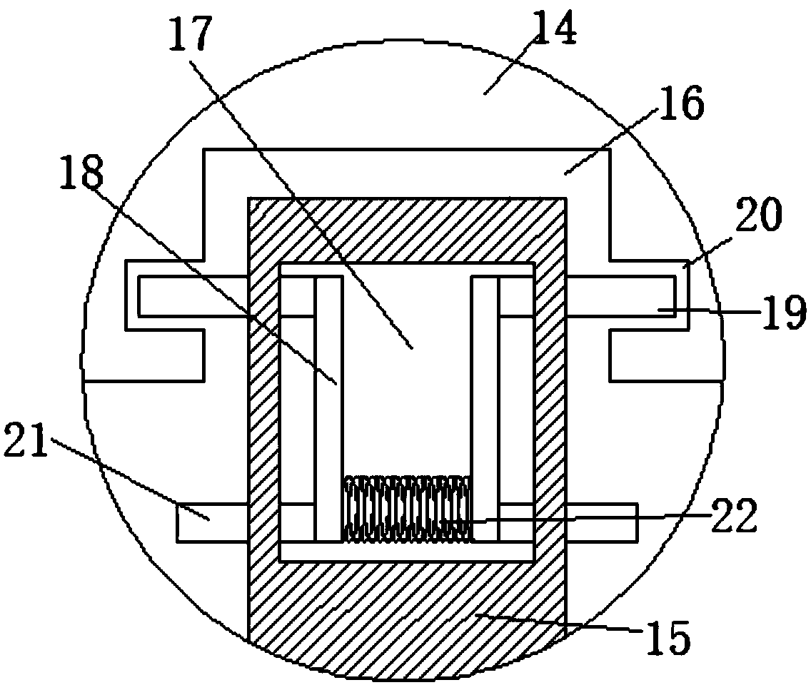
[0015] refer to Figure 1-3 , a pin pressing device, comprising a base 1, the base 1 is provided with a first rotating groove 2 arranged horizontally, and a first threaded rod 3 is rotatably connected to the first rotating groove 2, and one end of the first threaded rod 3 runs through the second A turning groove 2 is set, and the first threaded rod 3 is also sleeved with a first nut 4 matching it, and the side wall of the first nut 4 is also fixedly connected with the first connecting rod 5, and the upper side wall of the base 1 is also There is a strip-shaped opening communicating with the first turning groove 2, and the first connecting rod 5 is set through the str...
PUM
 Abstract
Description
Claims
Application Information