Drilling clamp for machining

A drilling jig and machining technology, which is applied in the direction of manufacturing tools, metal processing equipment, metal processing machinery parts, etc., to achieve the effect of improving work efficiency, reducing manual operation procedures, and reducing operating burden

Inactive Publication Date: 2018-02-23
上海瓜齐电子科技有限公司
View PDF1 Cites 0 Cited by
  • Summary
  • Abstract
  • Description
  • Claims
  • Application Information

AI Technical Summary

Problems solved by technology

[0004] Aiming at the deficiencies in the prior art, the purpose of the present invention is to provide a machined drilling jig to solve the problem of reducing time and manpower waste by fixing the connecting rod through the fixing buckle

Method used


Image

  • Drilling clamp for machining
  • Drilling clamp for machining

Examples


Embodiment Construction

[0018] In order to make the technical means, creative features, goals and effects achieved by the present invention easy to understand, the present invention will be further described below in conjunction with specific embodiments.

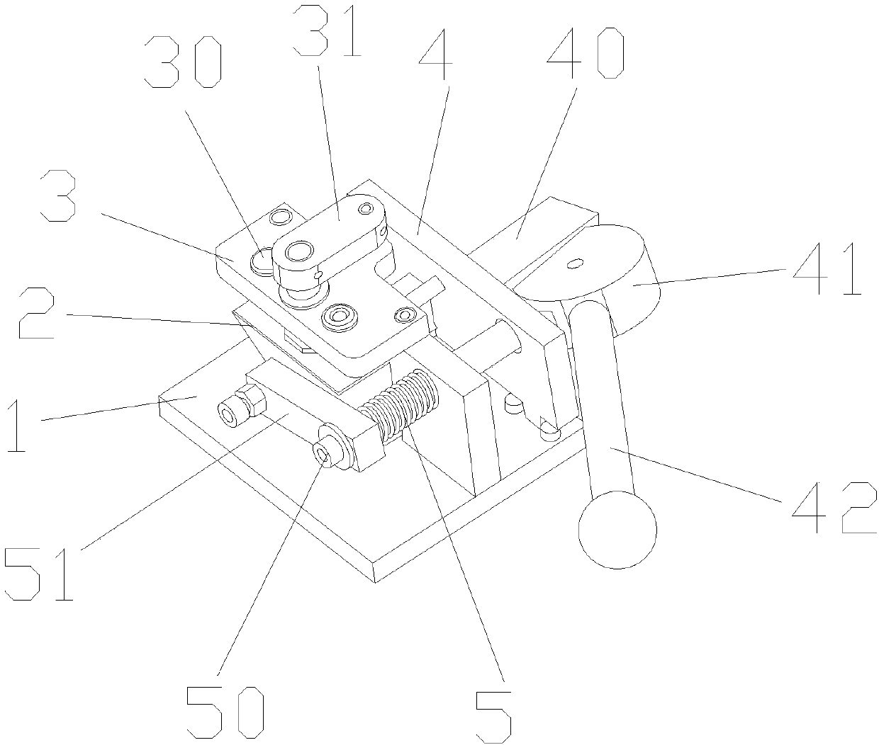
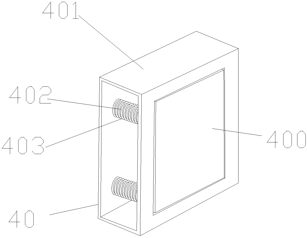
[0019] see Figure 1-Figure 2 , the present invention provides a technical solution: its structure includes a fixed base 1, a clamp 2, a fixed plate 3, a fixed frame 4, and a connecting spring 5. The clamp 2 is fixed below the fixed plate 3 through a nut, and is fixed by a nut. The fixed plate 3 is fixed above the inner side of the fixed frame 4 through nuts, the connecting spring 5 is arranged on the inner side of the fixed frame 4, the fixed base 1 is arranged below the fixed frame 4 through the fixed plate 3, and the fixed frame 4 is vertically connected to the Above the fixed base 1, the fixed plate 3 is connected in parallel with the fixed base 1 through the fixed frame 4, the clamp 2 is connected with the fixed frame 4 through the fixed plat...


PUM


Abstract

The invention discloses a machined drilling jig, the structure of which comprises a fixed base, a jig, a fixed plate, a fixed frame, and a connecting spring. Above the inside of the fixed frame, the connecting spring is arranged on the inside of the fixed frame, the fixed base is arranged under the fixed frame through the fixed plate, the fixed frame is vertically connected above the fixed base, the fixed plate is connected in parallel with the fixed base through the fixed frame, and the clamp is connected with the fixed plate through the fixed plate. The fixed frames are connected, the fixed plate is provided with tightening nuts and connecting blocks, the connecting block is fixed on the top of the fixing plate through nuts, and the tightening nuts are screwed on the inside of the upper part of the fixing plate through the connecting block with threads. When the hole fixture is used in processing, the connecting rod can be fixed by fixing the buckle, which reduces the manual operation procedure, reduces the operating burden for the operator, and is conducive to the improvement of work efficiency.

Description

technical field [0001] The invention is a machined drilling jig, which belongs to the field of drilling jigs. Background technique [0002] Machining, mechanical processing, mainly includes manual processing and numerical control processing. Manual processing refers to the method of processing various materials through manual operation of mechanical equipment such as milling machines, lathes, drilling machines and sawing machines. Refers to mechanical workers using numerical control equipment for processing. [0003] The prior art discloses a drilling jig with the application number of CN201220256058.9, which includes a base, a positioning device is provided on the base, and a transverse through hole is opened inside the positioning device, and one end of the through hole is connected with A support groove, the other end of the through hole is provided with a first clamping device, and the top of the support groove is provided with a second clamping device; the side of the ...

Claims


Application Information

Patent Timeline
Patent Type & Authority Applications(China)
IPC IPC(8): B23Q3/06
CPCB23Q3/06
Inventor 贺小玉
Owner 上海瓜齐电子科技有限公司
Why Eureka
Try Eureka